RSS Daily tech news
  • The hidden atomic gap that could break next-generation computer chips
    A major obstacle may be standing in the way of the next generation of ultra-tiny computer chips. Researchers discovered that many promising 2D materials lose their advantages because an invisible atomic-scale gap forms when they are combined with insulating layers. That tiny gap weakens electronic performance and could prevent further miniaturization. The team says new […]
  • Stanford’s new chip boosts light 100x with surprisingly low energy
    Researchers at Stanford have developed a compact optical amplifier that dramatically boosts light signals using very little power. By recycling energy inside a looping resonator, the device achieves strong amplification with minimal noise and wide bandwidth. Its efficiency and small size mean it could run on batteries and be integrated into consumer electronics. This breakthrough […]
  • Scientists capture electrons forming strange patchy patterns inside quantum materials
    Researchers have, for the first time, directly visualized how electronic patterns known as charge density waves evolve across a phase transition. Using cutting-edge microscopy, they found these patterns form unevenly, breaking into patches influenced by tiny structural distortions. Unexpectedly, small pockets of order persist even above the transition temperature. This reveals that electronic order fades […]
  • First ever atomic movie reveals hidden driver of radiation damage
    Researchers have visualized atoms in motion just before a radiation-driven decay process occurs, revealing a surprisingly dynamic scene. Instead of remaining fixed, the atoms roam and rearrange, directly influencing how and when the decay unfolds. This “atomic movie” shows that structure and motion play a central role in radiation damage mechanisms. The findings could improve […]
  • MIT scientists finally see hidden quantum “jiggling” inside superconductors
    MIT physicists have built a powerful new microscope that uses terahertz light to uncover hidden quantum motions inside superconductors. By compressing this normally unwieldy light into a tiny region, they were able to observe electrons moving together in a frictionless, wave-like state for the first time. This discovery opens a new window into how superconductors […]
  • A lab mistake at Cambridge reveals a powerful new way to modify drug molecules
    Cambridge scientists have discovered a light-powered chemical reaction that lets researchers modify complex drug molecules at the final stages of development. Unlike traditional methods that rely on toxic chemicals and harsh conditions, the new approach uses an LED lamp to create essential carbon–carbon bonds under mild conditions. This could make drug discovery faster and more […]

Pin diagram of the PIC16F877A microcontroller

by Florius
Illustration showing the 40-pin layout of the PIC16F877A microcontroller. Each pin is labeled with its corresponding port (e.g., RA0, RB7), alternate functions (such as ADC inputs, UART, SPI, I2C), and power supply pins (VDD, VSS). Used to guide hardware interfacing in MPLAB X IDE projects.

Pin diagram

The important pins

For accurate and dependable information, referring to the datasheets provided by Microchip Technology is advisable; these documents can be accessed here. Additionally, a brief overview of the pin diagram is recommended, detailing their functionalities and locations. Let’s begin by outlining the pins essential either for MCU operation or Pickit3 programmer-based programming:

  1. Pin 1 houses the MLCR/VPP, serving as a microchip reset mechanism.
  2. Pins 11 and 32, designated as VDD, necessitate a voltage range of 3.3V to 5V for proper functioning.
  3. Pins 12 and 31, denoted as VSS, are connecting to the ground
  4. To establish a connection with the Pickit3 programmer, pins 40 and 39 host PGD and PGC, respectively.
  5. Pins 13 and 14, namely OSC1 and OSC2, deliver a stable clock signal to the microcontroller. When utilizing the Pickit3 programmer, connecting these pins is unnecessary, thanks to the internal oscillator within the programmer facilitating MCU programming.

The exact method to program with your PICKIT3 programming tool, can be found here.

Pin diagram of the PIC16F877A; Programming pins
Pickit3 programming pins

Port structure in the PIC16F877A

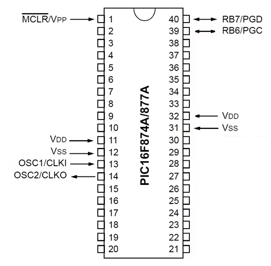
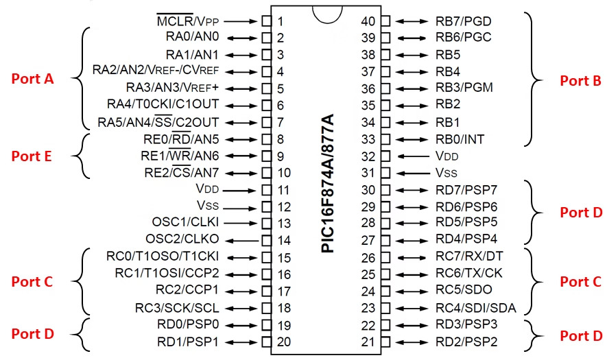
The PIC16F877A has 5 ports, namely A to E, where each pin can be configured as an input or output. However, it is important to note that not all ports consist of the same number of bits, due to some pins being taken by VSS or VDD, for example. In detail, port A consists of 6 bits, ports B, C, and D have 8 bits, while port E consists of only 3 bits.

Apart from being used for General Purpose Input Output (GPIO), most pins on this MCU have dedicated roles for specific functions. For instance, some pins on port C function as the TX and RX pins for the UART communication module, enabling the transmission and reception of serial data. Additionally, analog input channels for the ADC module on ports A and E can convert analog signals into digital values, opening up opportunities for further processing. When choosing IO pins, check the requirements of your project adequately to make the best possible decisions.

Labeled diagram of the PIC16F877A microcontroller showing all 40 pins with their port names (RA0–RA5, RB0–RB7, etc.), analog inputs, digital I/O, and special functions like USART, SPI, I2C, ADC, and oscillator pins. Useful for hardware design and firmware development in embedded applications.

Leave a comment

This site uses Akismet to reduce spam. Learn how your comment data is processed.