Using PWM in PIC16F877A
Digital signals (0 or 1) and analog signals (range of values) are both used in electronics. Analog inputs can be converted to digital through an ADC. To control analog devices with a microcontroller, DACs are used but they're costly and space-consuming. PWM (Pulse Width Modulation) is a cost-effective technique that ...
PIC16F877A Timer2 tutorial
The Timer2 module is an 8-bit timer/counter within most PIC MCU devices. Timer2 can increment up to a value of 255 before it overflows back to zero. Timer2 has other built-in features that make it very useful for many different applications.

PIC16F877A Timer1 Tutorial
The Timer1 module is a 16-bit timer/counter within most PIC MCU devices. Timer1 can increment up to a value of 65535 before it overflows back to zero. Because the timer is built into an 8-bit device, the 16-bit timer register is broken into two 8-bit registers (TMR1L and TMR1H) and ...

PIC16F877A Timer0 tutorial
The Timer0 module is an 8-bit timer/counter that is included with all 8-bit PIC MCU devices. The Timer0 is more than just a timer.

PIC Microcontrollers Timers
In this tutorial, we will learn what are "Timers"; we will explain this with examples using the Microcontroller PIC16F877A. For this tutorial is may be helpful to understand the basics of turning an LED on and off, which is explained in one of my previous tutorials on LEDs. In this ...

How to use interrupts in microcontrollers
In this tutorial we will learn how to use external interrupts in PIC microcontrollers. We will go in depth on how to set it up in hardware, and how to configure it correctly within the program. For the examples we will use microcontrollers from the PIC16F family; in particular the ...
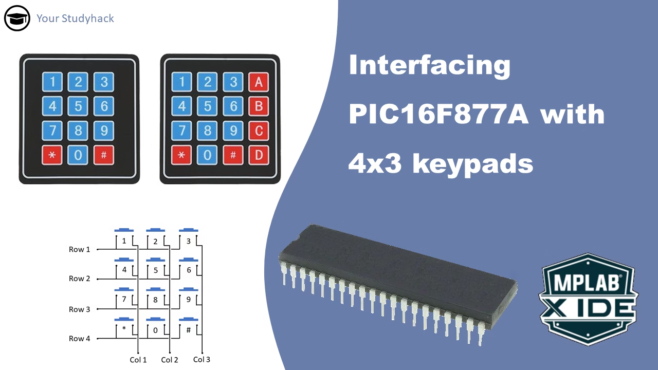
Interfacing 4×3 keypads with PIC16F877A
In this tutorial, we will provide an overview of the 4x3 membrane keypad. The keypad serves as a reliable and budget-friendly tool for having inputs in your project. Understanding how to interface with the keypad will prove useful in future projects that require menu selection or similar inputs. Our guide ...

Control Possibilities with PIC16F877A: Relays, Optos, H Bridges (Part 3 of 3)
Most microcontrollers have limited current sink or current source on their pins, including the PIC16F877A. However, certain projects may require larger currents than the maximum current source of 25mA for this microcontroller. As discussed in the previous two parts of this series, Bipolar Junction Transistors and MOSFETs can be used ...

Interfacing PIC16F877A with MOSFETS (Part 2 of 3)
Most microcontrollers have a limited current sink or current source on the pins, the PIC16F877A is no exception. However, for certain projects you may want to use larger currents then just 25mA, which is the max current source for this microcontroller. For those kind of projects you'll have to resort ...

Interfacing PIC16F877A with transistors (Part 1 of 3)
Most microcontrollers have a limited current sink or current source on the pins, the PIC16F877A is no exception. However, for certain projects you may want to use larger currents then just 25mA, which is the max current source for this microcontroller. For those kind of projects you'll have to resort ...