



The Timer0 module is an 8-bit timer/counter that is included with all 8-bit PIC MCU devices. The Timer0 is more than just a timer. It has all the following features:
- 8-bit timer/counter register (TMR0)
- 8-bit prescaler (mutually exclusive shared with Watchdog Timer)
- Programmable internal or external clock source
- Programmable external clock edge selection
- Interrupt on overflow
- TMR0 can be used to gate Timer1. This means that the ISR of timer0 can trigger Timer1 to start counting.
The Timer0 module has 2 distinct modes in which it can operate:
- Timer Mode: In Timer mode, Timer0 functions as a timer. It increments its value at a specified rate based on the clock source it’s configured to use. Once Timer0 reaches its maximum value (which depends on the number of bits it has), it overflows and generates an interrupt (or trigger an action, depending on the configuration). This overflow can be used to measure time intervals, generate periodic events, or trigger specific actions after a certain period.
- Counter Mode: In Counter mode, Timer0 functions as an external event counter. It counts the number of external pulses received on its input pin (usually T0CKI/T0CK) and increments its value accordingly. This mode is often used for applications where you want to count external events such as pulses from an external sensor, encoder, or any other source that generates discrete events.
The microcontroller series also have other timers, which can be used differently and separately from Timer0. I refer to the Timers in general, Timer1 and Timer2 for their respective information.
1. Timer mode
This is the mode we will focus on, even though the other mode might be just as interesting for certain applications. However, I will briefly mention how to configure the counter mode as well throughout the text. The other two important registers are:
| Registers | Description |
| OPTION_REG | This register is used to set the prescaler, using an ext. or int. clock source, edge select, etc. |
| TMR0 | This register holds the counter, from which the timer starts counting toward its max value. |

RBPU: N/A for timers
INTEDG: N/A for timers
T0CS: TMR0 Clock Source Select bit
1=Transition on RA4/T0CKI pin
0=Internal instruction cycle clock (CLKO)
T0SE: TMR0 Source Edge Select bit
1=Increment on high-to-low transition on RA4/T0CKI pin
0=Increment on low-to-high transition on RA4/T0CKI pin
PSA: Prescaler Assignment bit
1=Prescaler is assigned to the WatchDog Timer
0=Prescaler is assigned to the Timer0 module
PS2:PS0: Prescaler Rate Select bits
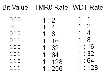
The timer mode is selected by setting T0CS = 0; whereas the counter mode can be selected by setting T0CS = 1, where additional external pulses have to be applied on the RA4/T0CKI pin. Another important bit is the PSA, which has to be set to 0, to select it for the Timer0 module. The three bits on the right of this, PS2:PS0 will give you 8 prescaler options, from 1:2 to 1:256.
1.1 TMR0 Register
The other important part of the timer mode is to set the timer to the correct delay that you want it to be. This is best explained in my overview tutorial on Timers where I use examples to calculate it. Nonetheless, I will give a short recap here as well. Timer0 requires you to set a Start number, from which it counts towards its maximum where it overflows. This start number can be calculated using the formula described below. Once calculated, it can be loaded in the TMR0 register in the code in hexadecimal format (e.g. TMR0 = 0x5C;).

2. Timer Interrupt
The TMR0IF interrupt flag bit of the INTCON register will be triggered after the TMR0 register overflows from FFh to 00h, irrespective of whether the Timer0 interrupt is enabled or not. The advantage of this is that the flag bit can be monitored by the software asynchronously. It is necessary to manually clear the TMR0IF bit as it is not reset by default.
In order to enable the automatic interrupt feature, the Timer0 interrupt enable bit (TMR0IE) of the INTCON register must be set to ‘1’. Furthermore, to turn on the interrupt globally, you’ll also need to set GIE and PIE bits in the INTCON register

GIE: Global Interrupt Enable bit
1=Enables all unmasked interrupts
0=Disables all interrupts
PIE: Peripheral Interrupt Enable bit
1=Enables all unmasked peripheral interrupts
0=Disables all peripheral interrupts
TMR0IE: TMR0 Overflow Interrupt Enable bit
1=Enables the TMR0 interrupt
0=Disables the TMR0 interrupt
INTE: NA for Timers
RBIE: NA for Timers
TMR0IF: TMR0 Overflow Interrupt Flag bit
1=TMR0 register has overflowed (must be cleared in software)
0=TMR0 register did not overflow
INTF: N/A for Timers
RBIF: N/A for Timers
3. Programming Code in MPLAB
For the PIC16F877A, with a crystal oscillator of 20 MHz, we will create a timer with Timer0, that blinks an LED every 1ms. The LED is situated on RD1. Using the formula above; with an 8-bit timer, the size is 256; for the prescaler we will use is 32; and the TimerCount calculated is 100 (0x64). Hence it starts counting at 100, and finishes at 256.
					#include <pic16f877a.h>
#include <xc.h>

#define XTAL_FREQ 20000000  // 20MHz external crystal oscillator frequency

// Configuration bits
#pragma config FOSC = HS    // High-Speed Crystal oscillator
#pragma config WDTE = OFF   // Watchdog Timer disabled
#pragma config PWRTE = OFF  // Power-up Timer disabled
#pragma config BOREN = OFF  // Brown-out Reset disabled
#pragma config LVP = OFF    // Low-Voltage Programming disabled
#pragma config CPD = OFF    // Data memory code protection off
#pragma config WRT = OFF    // Flash Program Memory Write protection off
#pragma config CP = OFF     // Flash Program Memory Code protection off

// Function prototype
void interrupt timer0_isr();

void main()
{
    TRISDbits.TRISD1 = 0;  // Configure RD1 (LED) as output

    OPTION_REG = 0b00100100;  // Timer0 with external freq source and 32 as prescalar
    TMR0 = 0x64;               // Load the time value for 1ms delay - Timer count is 100 (0x64)
    TMR0IE = 1;               // Enable Timer0 overflow interrupt bit
    GIE = 1;                  // Enable Global Interrupt
    PEIE = 1;                 // Enable the Peripheral Interrupt

    while (1)
    {
        // No need to toggle PORTD; only control RD1
    }
}

// Timer0 interrupt service routine
void interrupt timer0_isr()
{
    if (TMR0IF == 1)
    {
        RD1 = !RD1;       // Toggle RD1 (LED) state
        TMR0 = 0x64;       // Load the timer value for the next 1ms delay
        TMR0IF = 0;       // Clear Timer0 interrupt flag
    }
}

Florius
Hi, welcome to my website. I am writing about my previous studies, work & research related topics and other interests. I hope you enjoy reading it and that you learned something new.
More PostsYou may also like




Comments
Thanks for the article,
But need one clarification, isn’t writing to the TMR0 register in the interrupt routine will clear the Prescaler count and it’s mentioned in DS39582B-page 54
In my code, the prescaler is assigned to TMR0. This means that every time you write to TMR0, the prescaler count will be cleared. However, this does not change the prescaler assignment; it will remain assigned to TMR0.
Each time you write TMR0=0x64; within the ISR, the prescaler count is cleared to zero. This can cause a minor delay inconsistency due to the reset of the prescaler count. However, for most practical purposes and especially for simple applications like toggling an LED, this effect is negligible. The prescaler will simply restart its count from zero after every write to TMR0