
RSS Daily tech news
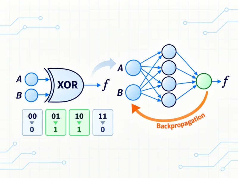
  • Ordinary WiFi can now identify people with near perfect accuracy
    Scientists in Germany have demonstrated a startling new form of surveillance: identifying people using nothing more than ordinary WiFi signals. By analyzing how radio waves bounce around a room, researchers can effectively “see” and recognize individuals — even if they are not carrying a device and even if their phone is turned off.
  • New quantum sensor could count individual photons and hunt dark matter
    Researchers have built an ultra-sensitive sensor capable of detecting unimaginably small amounts of energy — below one zeptojoule. The breakthrough relies on fragile superconducting materials that react to even the slightest temperature change. This level of precision could improve quantum computers, enable photon counting, and even help scientists detect elusive dark matter particles from space.
  • New quantum algorithm solves “impossible” materials problem in seconds
    A new quantum-inspired algorithm has cracked a problem so massive that conventional supercomputers struggle to even approach it. Researchers used the method to simulate extraordinarily complex quantum materials known as quasicrystals, opening the door to powerful new quantum devices and ultra-efficient electronics. The work could help scientists design advanced topological qubits and materials for future […]
  • The hidden atomic gap that could break next-generation computer chips
    A major obstacle may be standing in the way of the next generation of ultra-tiny computer chips. Researchers discovered that many promising 2D materials lose their advantages because an invisible atomic-scale gap forms when they are combined with insulating layers. That tiny gap weakens electronic performance and could prevent further miniaturization. The team says new […]
  • Stanford’s new chip boosts light 100x with surprisingly low energy
    Researchers at Stanford have developed a compact optical amplifier that dramatically boosts light signals using very little power. By recycling energy inside a looping resonator, the device achieves strong amplification with minimal noise and wide bandwidth. Its efficiency and small size mean it could run on batteries and be integrated into consumer electronics. This breakthrough […]
  • Scientists capture electrons forming strange patchy patterns inside quantum materials
    Researchers have, for the first time, directly visualized how electronic patterns known as charge density waves evolve across a phase transition. Using cutting-edge microscopy, they found these patterns form unevenly, breaking into patches influenced by tiny structural distortions. Unexpectedly, small pockets of order persist even above the transition temperature. This reveals that electronic order fades […]
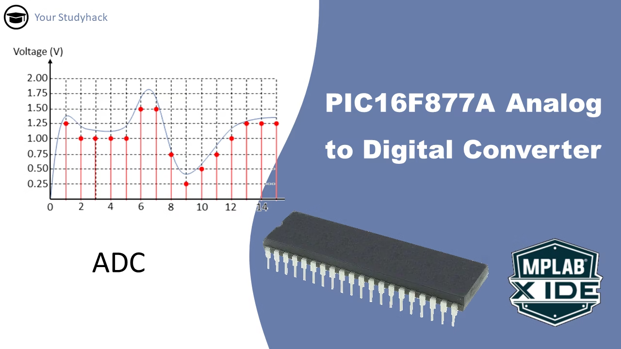
Educational graphic showing the analog-to-digital conversion (ADC) process using the PIC16F877A microcontroller. On the left is a graph of a smooth analog voltage waveform sampled at discrete points (shown as red dots), and on the right is the PIC16F877A chip with MPLAB X IDE branding. The image illustrates how analog voltages are digitized for processing in microcontroller-based systems.

PIC16F877A Analog to Digital Converter (ADC)

The ADC module in microcontrollers indeed allows them to interface with the analog world by converting continuous analog signals into discrete digital values. This capability is crucial for various applications such as sensing, control systems, and communication. It is distinct from PWM (Pulse Width Modulation), which uses discrete pulses to ...
Graphical illustration of PWM signal showing narrow and wide pulses with varying duty cycles. Includes a 10V signal graph, labels for voltage levels, and mentions PIC16F877A microcontroller and MPLAB X IDE.

Using PWM in PIC16F877A

Digital signals (0 or 1) and analog signals (range of values) are both used in electronics. Analog inputs can be converted to digital through an ADC. To control analog devices with a microcontroller, DACs are used but they're costly and space-consuming. PWM (Pulse Width Modulation) is a cost-effective technique that ...
Educational slide introducing Timer2 of the PIC16F877A microcontroller. It includes a stopwatch icon with the phrase “Alarm, Timers, how does it work?” on the left, and an image of the PIC microcontroller with MPLAB X IDE branding on the right. The tutorial focuses on Timer2's use in generating precise delays and pulse-width modulation (PWM).

PIC16F877A Timer2 tutorial

The Timer2 module is an 8-bit timer/counter within most PIC MCU devices. Timer2 can increment up to a value of 255 before it overflows back to zero. Timer2 has other built-in features that make it very useful for many different applications.
Educational slide introducing the Timer1 module of the PIC16F877A microcontroller. The left side shows a stopwatch icon and the question “Alarm, Timers, how does it work?”, while the right side features the microcontroller image and MPLAB X IDE logo. The tutorial focuses on Timer1's role in timing, delays, and interrupts.

PIC16F877A Timer1 Tutorial

The Timer1 module is a 16-bit timer/counter within most PIC MCU devices. Timer1 can increment up to a value of 65535 before it overflows back to zero. Because the timer is built into an 8-bit device, the 16-bit timer register is broken into two 8-bit registers (TMR1L and TMR1H) and ...
Educational slide introducing the use of hardware timers in the PIC16F877A microcontroller. The left side features a stopwatch icon and the question “Alarm, Timers, how does it work?”, while the right side shows the microcontroller and MPLAB X IDE logo. The image sets the stage for learning about Timer0, Timer1, and Timer2 functionality.

PIC Microcontrollers Timers

In this tutorial, we will learn what are "Timers"; we will explain this with examples using the Microcontroller PIC16F877A. For this tutorial is may be helpful to understand the basics of turning an LED on and off, which is explained in one of my previous tutorials on LEDs. In this ...
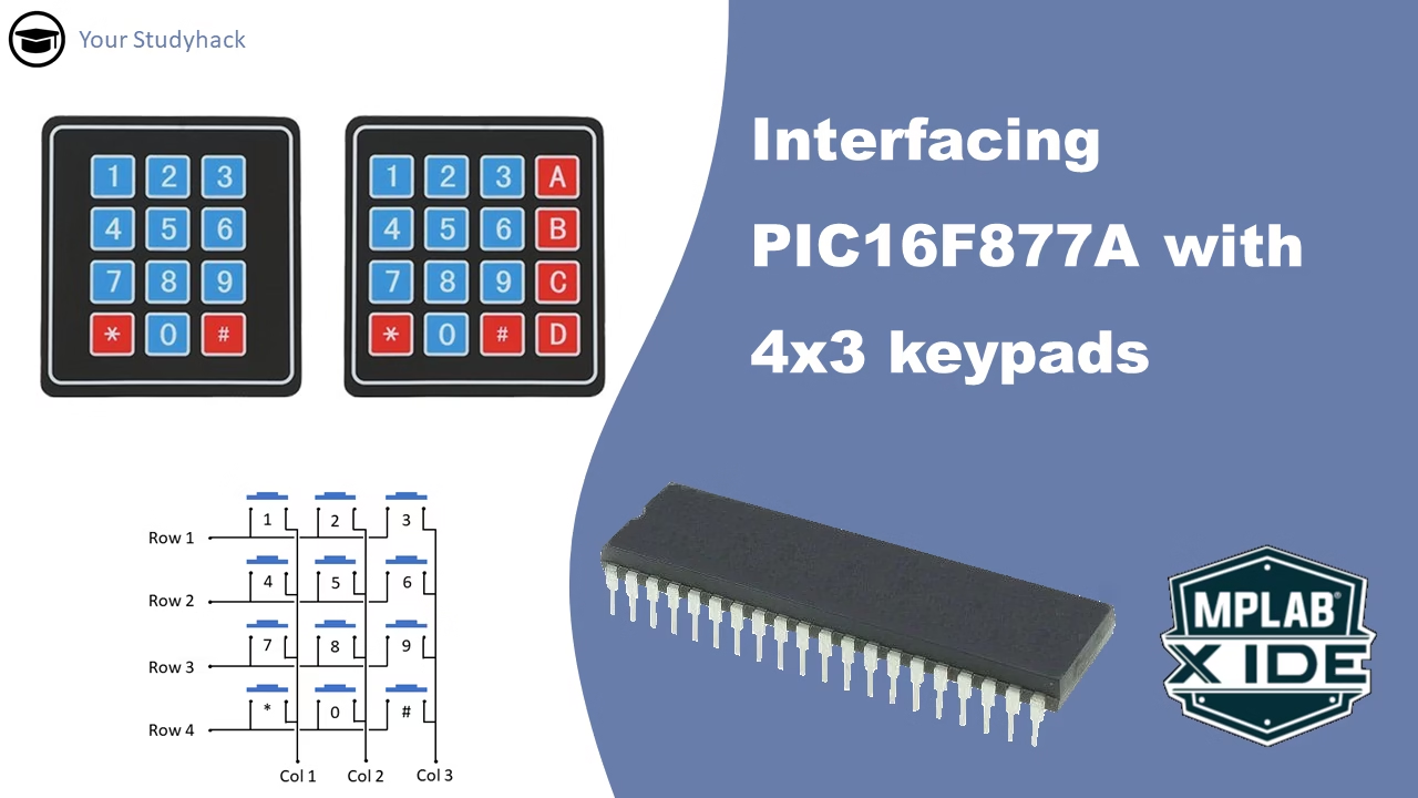
Educational graphic showing how to interface 4x3 matrix keypads with a PIC16F877A microcontroller. The image includes two physical keypads, a schematic layout of the 4x3 keypad connections, the PIC16F877A chip, and the MPLAB X IDE logo. Text reads "Interfacing PIC16F877A with 4x3 keypads."

Interfacing 4×3 keypads with PIC16F877A

In this tutorial, we will provide an overview of the 4x3 membrane keypad. The keypad serves as a reliable and budget-friendly tool for having inputs in your project. Understanding how to interface with the keypad will prove useful in future projects that require menu selection or similar inputs. Our guide ...
Categories
Instagram