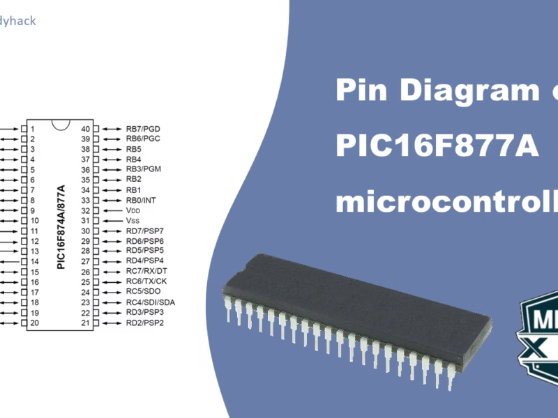
In this tutorial, we will learn what are “Timers”; we will explain this with examples using the Microcontroller PIC16F877A. For this tutorial is may be helpful to understand the basics of turning an LED on and off, which is explained in one of my previous tutorials on LEDs. In this tutorial we will cover the 3 different timers in PIC16F877A, and explain the calculations in detail. For more in-depth knowledge of each particular timer of the PIC16F877A, please go to the dedicated page:
1. How are timers made?
Timers are somewhat similar to alarm clocks; they keep track of the time and warn you. You can set an alarm after a certain amount of time, and multiple alarms can be set independently. Similarly, microcontrollers can have multiple timers that count independently and can be programmed to perform different tasks when they reach their specified intervals. An alarm clock will warn you (to wake up most likely). Similarly, a timer can generate an interrupt to interrupt the main program and execute a specific action (handled by an interrupt service routine) before returning to the main program.
In essence, a timer in a microcontroller is nothing more then a counter, that is triggered by clock pulses. Once it reaches its maximum value, it’ll overflow and reset back to 0. At this time it also generates an interrupt.
Below is a simplified block diagram of a timer.
A timer is made of some electronic devices that use the main clock pulse as input. It consists of a pair of MUX’s, AND gates, and sometimes prescalers, counters, flipflops and postscalers.
As shown in the animated block diagram above, the working of a timer can be boiled down to the following steps:
- The first Multiplexer (MUX), will select if you use an external or internal clock
- The second MUX will select if you want to use a preset prescalar, or use the actual clock pulse. A prescaler will increase the period of the clock pulse.
- The AND gate, will check if the specific timer is enabled.
- The Timer counter will start counting the clock pulses (high to low, or low to high). Certain timers have an 8-bit counter, others 16-bits.
- In this case, at 0xFF, the next pulse will cause an overflow. The counter itself will reset. Additionally, an overflow interrupt flag is typically set when this overflow occurs.
1.1 Timers vs Delay
Most beginning programmers, will learn how to use a microcontroller to blink a LED every 1 second. This is a useful exercise, but is very limited in practical applications. The particular __Delay_ms() function, can also be used to create a timer of 1 second, but when using this function, the MCU is just focused on performing that delay task, and cannot do anything else; such as setting registers, reading data on the TX lines, or listening to ADC values coming in. Most likely, the only time you truly want to use delay functions is when you have a simple program to blink LEDs and that is it.
There are few other shortcomings as well in using delay functions. The most important one is that these functions are not as accurate as timers, and large delays (e.g. half hour) can not be created by these functions.
2. Timers in PIC Microcontrollers
It’s important to know that microcontrollers have their own built-in clocks. These clocks can be internal (inside the microcontroller) or extermal (crystal oscillator). In our case, we use crystal oscillators that create a steady clock signal that the microcontroller needs, to work properly. This clock sets the pace for running programs on the microcontroller. It’s like the conductor of an orchestra, making sure everything stays in sync.
For microcontrollers that come with timers, there’s a kind of built-in counter that keeps ticking as time goes by. However, there’s a limit to how much these timers can count. They can go from 0 to either 255 (if it’s an 8-bit timer) or 65535 (for a 16-bit timer). Just to give you an idea, these counts are way smaller than the 20,000,000 ticks per second that a 20 MHz crystal produces.
When the value of an 8-bit timer register surpasses 255, it wraps around and resets back to zero. This occurrence is referred to as a timer overflow. Each time a timer register overflows, a special function known as the Timer Interrupt Service Routine (ISR) begins its execution. Similarly, in the case of a 16-bit timer, the Timer ISR is triggered when the timer’s value exceeds 65,535.
The Timer ISR always takes precedence, no matter the ongoing tasks or functions of your microcontroller. It triggers regardless of the microcontroller’s current activities. So, whenever a timer overflow occurs, you can be certain that the Timer ISR will be launched.
2.1 Clock divider by 4
PIC 16 microcontrollers are equipped with built-in hardware that divides the frequency of an external crystal oscillator by 4. This means that if you connect a 20 MHz crystal externally, the hardware effectively treats it as if it were a 4MHz crystal due to this division by 4.
2.2 Prescaler
To enhance flexibility, the microcontroller has another feature known as prescaling. Prescaling provides a way for the timer to skip a set number of microcontroller clock ticks before incrementing. In simpler terms, instead of increasing the timer register for every single tick from the microcontroller’s clock, we can set it to increase after 8, 64, or 256 ticks, among other options.
“For example if the value of prescaler is 64, then for every 64th pulse the Timer will be incremented by 1.”
We can use the Prescaler for further division of the system clock. Depending on the microcontroller and the timer, the possible options are:
- 1:2
- 1:4
- 1:8
- 1:16
- 1:32
- 1:64
- 1:128
- 1:256
2.3 Postscaler
Similar to the prescaler, some Timers have an additional feature called Postscaler. Where the prescaler is done before the counter, the postscaler is done afterwards. Normally the timer overflow would trigger an interrupt, however in this case, the postscaler is incremented and its output is used to generate an interrupt if it is enabled. Creating another method to increase the timer duration. For the PIC16F877A, this option is only available for TMR2, and the possible states are:
- 1:1
- 1:2
- 1:3
- 1:15
- 1:16
3. Delay calculation
Every timer requires a Start number and End number, and a counter that starts counting from start to end in an unending loop, with an overflow at every end. Through prescalers and postscalers, you can slow down the frequency of the interrupts. For the PIC16 family, there are 2 (as far as I know) types of timers:
- For the first type, you have a fixed End number, and can change the Start number. E.g. you can move it closer to the end, if you want a shorter timer.
- For the second type, you have a fixed Start number and you can change the End number. In a similar fashion, you can reduce the time by lowering the End number.
3.1 Example of Timer1
Let’s start with an example of the first type, with a fixed End and a changeable Start number. We have an external frequency of 20MHz, we require a delay of 100 ms and we use a 16-bit timer1 (0 to 65535)
\[\text{f}_\text{clk} = 20 \text{MHz}\]
For most of the PIC microcontrollers, like the PIC16F877A, there is often a division by 4 applied to the external clock source (fclk) when it’s fed into the internal clocking system. This division by 4 is not a literal division of the crystal oscillator frequency itself, but rather a characteristic of the microcontroller’s internal clocking structure. This division by 4 aligns the external clock frequency with the requirements of the microcontroller’s internal operations and peripheral modules.
\[\text{f}_\text{instr} = \frac{20\text{MHz}}{4} = 5 \text{MHz}\]
The time for a single instruction clock cycle is then calculated as follows:
\[\text{T}_\text{instr} = \frac{4}{\text{f}_\text{clk}} = \frac{1}{5 \text{MHz}} = 0.2\times 10^{-6} s\]
For this example we require a delay of 100 ms, which requires a certain amount of Tinstr:
\[\text{TimerCount} = \frac{T_{delay}}{T_{instr}} = \frac{100\times 10^{-3}}{0.2\times 10^{-6}} = 500000\]
This is larger than the size of TIMER1’s counter (of 65536). Hence we need a prescaler, that can further reduce this. Here we use a prescaler of 32:
\[\text{TimerCount} = \frac{T_{delay}}{(prescaler \times T_{instr})} = \frac{100\times 10^{-3}}{32\times 0.2\times 10^{-6}} = 15625\]
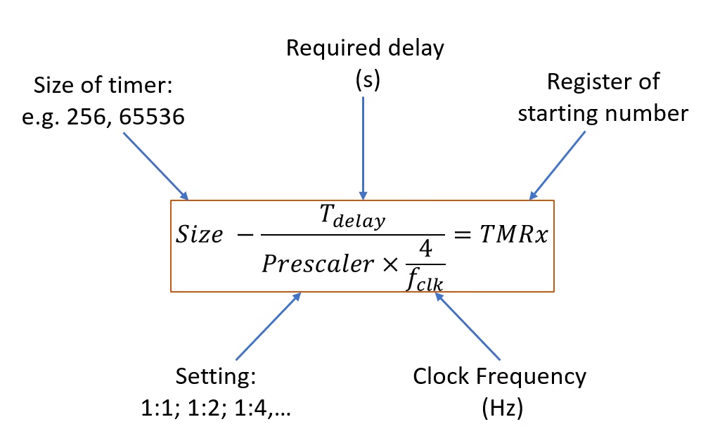
With this, we only need to count 15625 ticks. Now the tricky part is, the timer will overflow at MAX value of 65535, and it only needs to count 15625 ticks, that means we have to start somewhere three quarters of the way. We calculate that by the following:
\[\text{TMR1} = \text{Size} – \text{TimerCount} = 65536 – 15625 = 49911\]
49911 is the value we have to load into the TMR1 register. We have to convert it first into an hexadecimal number: 0xC30F. Because the register can only contain 2 bytes, we use 2 registers for the high and low parts. We load the higher 2 digits in TMR1H, and the lower 2 digits in TMR1L. Note that in certain occasions, you receive an hexadecimal number of only 3 (or 2) digits. In that case, add an additional zero. E.g. 0xE49 will be 0x0E49
If you know the clock frequency and the delay, you will have to make a decision which timer you will use and what prescaler to set. Obviously, an 8-bit timer is limited, but for the PIC16F877A, there is only one 16-bit timer, so choose wisely.
Florius
Hi, welcome to my website. I am writing about my previous studies, work & research related topics and other interests. I hope you enjoy reading it and that you learned something new.
More Posts