For decades, the PID control system has stood as one of the industry’s most established and widely adopted strategies, owing to its straightforward yet efficient algorithm. Within this article, we’ll delve into the fundamental concept of the PID controller and explore how to imbed it into microcontrollers.
1. System transfer functions
Normally when talking about amplifiers, it is customary to talk of the gain of the amplifier. The gain means how much bigger the output is compared to the input signal. As example, when an amplifier has a gain of 10, and apply an input of 2 mV, the output will be 20 mV. It is a mathematical relationship between the output and input of a certain “block”.
\[\text{Gain} = \frac{\text{output}}{\text{input}}\]
However, for many systems, the output and input have a relationship that has the form of a differential equation, and thus the statement that it is a simple algebraic division between two numbers is not possible (e.g. gain = 10). To solve this, we can transform a differential equation into an algebraic equation by using a Laplace transformation. The difference is that differential equations describe how it behaves in time, while Laplace equation takes out the time part. Hence, they are being transformed from the time domain to the s-domain. Now the relationship between the output and input can be defined as a transfer function:
\[\text{Transfer function} = \frac{\text{Laplace(output)}}{\text{Laplace(input)}}\]
There is a small difference in notation; when in the time domain, a function of time is normally written as f(t). While in the s-domain, we have functions of s, written as F(s), with a capital F for the Laplace transform.
Let’s consider a linear system represented by a block diagram, with input signal Y(s) and output signal X(s). The transfer function G(s) of this system is defined as
\[G(s) = \frac{X(s)}{Y(s)}\]
After performing algebraic manipulations in the s-domain, the resultant equation can be converted back into the time domain using inverse transformations. A helpful resource for these conversions between the time and s-domain can be found on the following website: Wiki: Laplace transform.

1.1 First-order systems
A first-order system refers to a dynamic system whose behavior can be adequatly described by a first-order ordinary differential equation (ODE) or transfer function. It typically represents a system with one energy storage element. Examples are:
- RC Circuits,
- Thermal systems,
- Many chemical reactions,
- Many population dynamics.
The differential equation has the form of:
\[a_1 \frac{dx}{dt} + a_0 x = b_0 y\]
where a1, a0, b0 are all constants and y is the input and x is the output, both being a function of time. Transforming this to the s-domain gives the following:

\[a_1 sX(s) +a_0 X(s) = b_0 Y(s)\]
With this algebraic equation we can write the transfer function G(s):
\[G(s) = \frac{X(s)}{Y(s)} = \frac{b_0}{a_1 s+a_0}\]
which is further rearranged to:
\[G(s) = \frac{b_0/a_0}{(a_1/a_0)s+1} = \frac{G}{\tau s+1}\]
where G is the gain of the system when steady-state has been reached, and τ is the time constant of the system.
If a system consists of several of these blocks, each with its own unique gains, than the transfer function of the whole system is given by:
\[G(s) = \frac{X_1(s)}{Y(s)}\times\frac{X(s)}{X_1(s)} = G_1(s)\times G_2(s)\]
1.2 Systems with feedback loops
Figure 3 shows what happens when a system has negative feedback. This means that the input signal and the feedback signal are subtracted at the summation block. There are two important terms here that should be understood:
- The term Forward path is for the path that has the transfer function G(s),
- The term Feedback path is for the path that has the transfer function H(s).
- Closed-loop system entails the entire system.

The feedback loop has a transfer function H(s) and an input X(s); thus the feedback signal is H(s)X(s). The input for the forward path with G(s), is Y(s) minus the feedback signal that we just found as H(s)X(s). Thus the input for G(s) is (Y(s) – H(s)X(s)) and an output of X(s). Thus the whole transfer function will be:
\[G(s) = \frac{X(s)}{Y(s)-H(s)X(s)}\]
which can be arranged to:
\[T(s) = \frac{X(s)}{Y(s)} = \frac{G(s)}{1+G(s)H(s)}\]
which is the overal transfer function of the system T(s).
1.2.1 Transient and Frequency response
The transient response deals with step functions and unit impulses, while the frequency response tells you more about actual sine wave responses. I will briefly talk about transient responses and omit frequency response altogether, as this topic requires more than a single post.
When you subject a first-order system (without feedback) with a unit impulse as input, the output will respond accordingly. The transform of a unit impulse signal at t = 0 has a transform of 1. The output X(s) = 1/(s+1) is in the time domain x = e-t , and will decay to zero for large values of t.
What will happen if the same unit impulse is applied to a system with the transfer function X(s) = 1/(s-1) ? The output will then be in the time domain x = et. As t increases, the output will go to infinity, and the system with this pole is unstable. In general, a first-order system with a transfer function 1/(s+p) will be stable if the pole p is positive and become unstable if p is negative. In system dynamics, you will come across the terms poles and zeros often. If we write the transfer function with numerator N(s) and denominator D(s):
\[H = \frac{N(s)}{D(s)}\]
then the zeros (zi‘s) are the roots of the equation N(s) = 0 and the poles (pi‘s) are the roots of the equation D(s) = 0. There is a lot of theory on this topic as the position of the poles and zeros tell you something about the stability of the system. Using software such as MATLAB and SIMULINK can help you plot the pi‘s and the zi‘s in a complex plane from where you can determine the stability of the system. But this is something out of the scope for this article.
Sometimes adding another zero or pole can increase the stability of the system, but it will change the transfer function. Hence, measures should be taken to keep the stability (e.g., the gain parameters of a PID controller should be adjusted for the change in the transfer function).
2. PID controller
This section gives a brief recap of PID control theory, the PID architecture and the formulas to implement it in C++. A basic understanding of Laplace and Z-transformation is a prerequisite. We start with assuming that all signals are a function of a continuous-time variable t. Originally, the PID controller is made up of analog devices, that work in the time domain. In a later section we will discretize this continuous-time that can easily be implemented into microcontrollers.
2.1 Continuous-Time
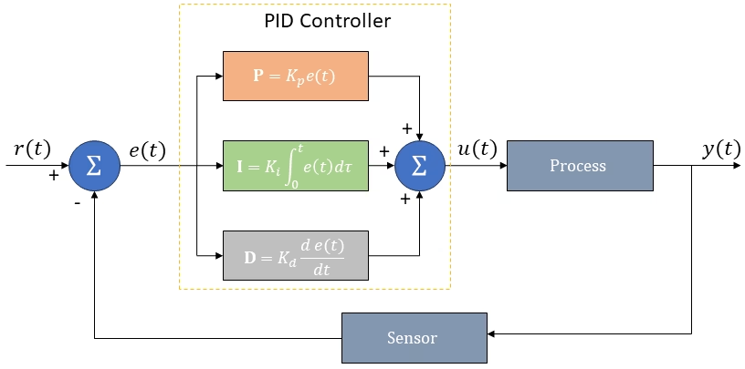
In a PID controller, the control signal, u(t), is calculated as the sum of three components, a proportional, an integral and a derivative component. The Proportional (P) component simply multiplies the error with a constant Kp, the integral term multiplies the the time integral of the error by a constant Ki, and finally, the derivative term multiplies the derivative of the error by a constant Kd. Mathematically, the PID Control equation is given by:
\[u(t) = K_pe(t)+K_i\int^t_0e(\tau)d\tau+K_d\frac{de(t)}{dt}\]
where
Kp is the proportional gain,
Ki is the integral gain,
Kd is the derivative gain,
e(t) is the error,
t is the time,
τ is a variable of integration between 0 and t.
In industry, the above equation is sometimes rewritten in terms of integral time Ti, and derivative time Td, as it is more intuitive. the integral component compensates for the sum of the past errors, with the intention of removing them in Ti seconds. The derivative term attempts to predict the error value at Td seconds in the future, if nothing changes. In this case, the equation is the following:
\[u(t) = K_p\left(e(t) +\frac{1}{T_i}\int^t_0e(\tau)d\tau +T_d\frac{d}{dt}e(t)\right)\]
2.1.1 How to tune the PID controller
Fine-tuning a closed-loop PID system entails adjusting the control parameters to achieve optimal responsiveness. While stability stands as a paramount requirement, the diverse nature of systems introduces varying and occasionally conflicting demands. Crafting and refining a PID controller proves challenging, given the multitude of components and adjustments involved.
Moreover, despite often designing systems under the assumption of linearity, many processes exhibit nonlinear behavior. Tuning parameters tailored to a specific load may falter during startup or under drastically different operating conditions. To address this, gain-scheduling emerges as a solution, allowing for the adaptation of tuning parameters across different operational regimes. However, abrupt parameter changes can potentially destabilize the system, underscoring the importance of gradual adjustments to maintain stability and ensure smooth transitions.
Various tuning methods exist for both open-loop and closed-loop systems. These methods involve inducing a change in the system without employing a PID controller and observing the resultant process response. By analyzing these characteristics, we can deduce the appropriate control parameters.
When it comes to tuning a PID controller, you have three distinct avenues to explore:
- Manual tuning: This method involves a hands-on approach without the need for intricate mathematics. You adjust the parameters intuitively until the system’s response aligns with your satisfaction.
- Rule-based tuning: Techniques such as Ziegler-Nichols, Cohen-Coon, and Astrom-Hagglund rely on applying a step response to the input and analyzing the resulting process response characteristics to determine the control parameters.
- Model-based tuning: Utilizing a mathematical model, typically expressed in terms of differential equations, that accurately represents your system allows for precise design adjustments facilitated by computer programs.
2.2 Discrete-Time
In practice, microcontrollers are nowadays almost exclusively implemented digitally. This means that the microcontroller operates in discrete time, although the controlled systems usually operate in continuous time. To incorporate it, we need depart from continuous-time signals and the corresponding Laplace transformrations. Instead, the focus shifts to managing discrete-time signals and their Z-transformations, reflecting the practicalities of data acquisition through analog-to-digital converters (ADCs) and the imperative of sampling at discrete intervals.
The PID controller registers the process signal through an AD converter as input, and generates an output at each time step. The DAC has to convert it back into analog. The signal is held constant during the present time step, hence becoming a staircase signal. The time step is small compared to the time constant of the process itself, so it does not feel the staircase form on its input.
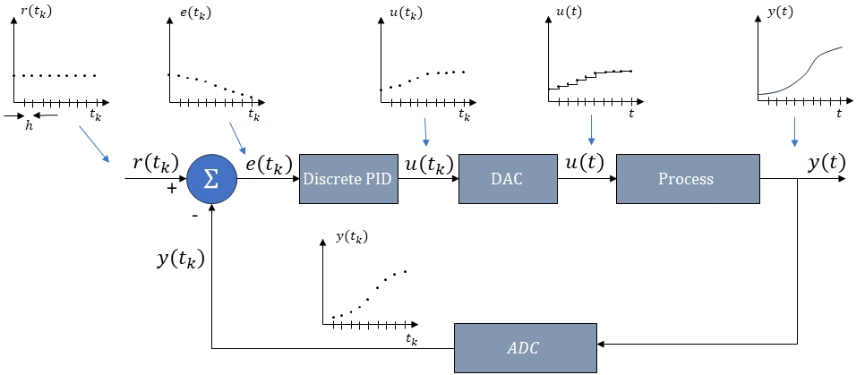
The discrete-time PID controller equation is implement in the velocity form, because it has some advantages compared to the position form. The choice between the position and velocity forms depends on the specific system and desired control behavior. In general, the velocity form is preferable when:
- Smooth response to parameter changes is important.
- Integral windup is a concern.
- Setpoint changes are frequent.
- Noise is primarily low-frequency.
The position form may be preferred when:
- High steady-state accuracy is critical.
- The system requires integral action.
- High-frequency noise is a significant concern.
The incremental algorithm (velocity form) is based on splitting the calculation into two steps:
- First the incremental control value, Δu(tk), is calculated.
- Afterwards the absolute control value, u(tk), is calculated by adding the difference with the previous value.
Thus, the two equations of the PID controller are as follows:
\[\Delta u(t_k) = K_p \left[ e(t_k) – e(t_{k-1})\right] + \frac{K_pT_s}{T_i} e(t_k) + \frac{K_pT_d}{T_s}\left[e(t_k) – 2e(t_{k-1}) + e(t_{k-2})\right]\]
\[u(t_k) = u(t_{k-1}) + \Delta u(t_k)\]
where,
tk = discrete time (0, 1, 2, 3,..),
u(tk) = the control value at time k
e(tk) = Error at time k
Kp = Proportional Gain
Ti = Integral time
Td = Derivative time
Ts = Sample time
2.2.1 Sampling time
the DA converter, which is always implemented between the discrete PID controller and the continuous-time process, holds the calculated signal during the sample time (or time step Ts). This means, that the control signal now has a delay of Ts / 2, as shown in the figure. This delay influences the stability of the system.
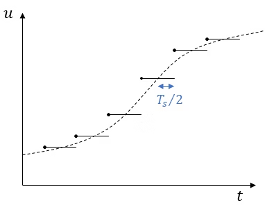
Suppose we use the tuning methods in a computer model that is based on a continuous-time PID controller. And now we implement these tuning parameters on the discrete-time PID controller. We will have a reduced stability, because of this additional delay of Ts / 2. As a rule of thumb, the stability reduction is tolerable if the time delay, is less then one tenth of the response time of the control system, as it would be in the case of the continuous-time controller.
\[\frac{T_s}{2} < \frac{T_r}{10}\]
which results in
\[T_s < \frac{T_r}{5}\]
The response time can be calculated by using a step function on the input, and you read off at where the rise time is 63% of the total output. In systems where the time constant, $\tau$, is dominant, the response time is approximately equal.
2.2.3 Integrator anti-windup
Large disturbances or setpoints may cause the PID controller to saturate, reaching its maximum output and becoming clamped. An illustrative scenario is encountered with an analog-to-digital (AD) converter, where the output range is constrained from 0 to 255. However, the PID controller is unaware of this limitation and may erroneously compute an output exceeding this range. Consequently, the cumulative error continues to accumulate, leading to a continuous increase in the integral term, commonly referred to as integral windup.
When the disturbance subsides and the system returns to its normal state, the integral windup necessitates a gradual wind-down process, further prolonging the response time. During this period, the calculated output may persistently surpass its physical maximum, resulting in an additional delay.
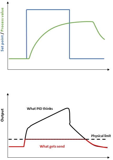
To mitigate the integral windup issue, various methods can be employed. One effective approach is to halt the integration of the error when the calculated output exceeds a predefined threshold (e.g., 255 in the case of an ADC). This action prevents the integral term from further inflating the output, thereby bringing it closer to the actual maximum. Although there may still be slight overshoots attributable to the proportional (P) and derivative (D) terms, it is predominantly the integral (I) term that tends to push the output beyond its permissible limit.
3. Code
We can use the discretized equation, described before, to implement the PID controller in the microcontroller. The following code has been created by Brett Beauregard, more information on him on his personal website.
					/*working variables*/
unsigned long lastTime;
double Input, Output, Setpoint;
double ITerm, lastInput;
double kp, ki, kd;
int SampleTime = 1000; //1 sec
double outMin, outMax;
void Compute()
{
   unsigned long now = millis();
   int timeChange = (now - lastTime);
   if(timeChange>=SampleTime)
   {
      /*Compute all the working error variables*/
      double error = Setpoint - Input;
      ITerm+= (ki * error);
      if(ITerm> outMax) ITerm= outMax;
      else if(ITerm< outMin) ITerm= outMin;
      double dInput = (Input - lastInput);

      /*Compute PID Output*/
      Output = kp * error + ITerm- kd * dInput;
      if(Output > outMax) Output = outMax;
      else if(Output < outMin) Output = outMin;

      /*Remember some variables for next time*/
      lastInput = Input;
      lastTime = now;
   }
}

void SetTunings(double Kp, double Ki, double Kd)
{
  double SampleTimeInSec = ((double)SampleTime)/1000;
   kp = Kp;
   ki = Ki * SampleTimeInSec;
   kd = Kd / SampleTimeInSec;
}

void SetSampleTime(int NewSampleTime)
{
   if (NewSampleTime > 0)
   {
      double ratio  = (double)NewSampleTime
                      / (double)SampleTime;
      ki *= ratio;
      kd /= ratio;
      SampleTime = (unsigned long)NewSampleTime;
   }
}

void SetOutputLimits(double Min, double Max)
{
   if(Min > Max) return;
   outMin = Min;
   outMax = Max;

   if(Output > outMax) Output = outMax;
   else if(Output < outMin) Output = outMin;

   if(ITerm> outMax) ITerm= outMax;
   else if(ITerm< outMin) ITerm= outMin;
}
Florius
Hi, welcome to my website. I am writing about my previous studies, work & research related topics and other interests. I hope you enjoy reading it and that you learned something new.
More Posts


