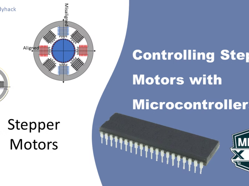
1. Introduction to Stepper Motors
The basic principle behind a motor lies in the conversion of electrical energy into rotational mechanical movement. This can manifest as either continuous or step-wise rotation, allowing for precise control. In this context, the stepper motor stands out for its ability to stop at any given position and maintain it.
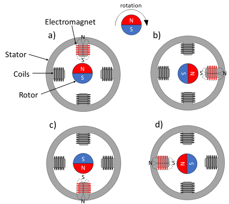
The stepper motor comprises of two essential components: the rotor, which is the rotating part, and the stator, which remains stationary. The rotor typically consists of a permanent magnet, featuring a north (N) and a south (S) pole. The basic components, and how it is able to rotate is shown in Figure 1 (a) – (d)
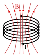
The stator, on the other hand, plays a pivotal role in this process. It is equipped with wires that, when energized, generate electromagnetic fields. By strategically arranging these wires in coils, we can amplify and direct these fields as is shown in Figure 2. This transformation allows specific segments of the stator to become electromagnets. When activated, these electromagnets exert forces on the permanent magnet of the rotor. This interaction leads to controlled rotation. This process is shown in Figure 1. The frequency of switching speeds up the process, and because these switches are electrical signals, they can therefore be programmed with a microcontroller.
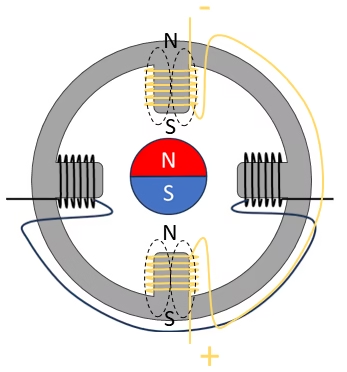
Different stepper motors exist, which we will go into more detail down below. However, even for the simplest case that we just discussed, people found ways to optimize it further. One of the defining characteristics of stepper motors is their torque, which is the rotational force they can exert. This torque allows them to move loads with precision and accuracy. Instead of energizing a single coil to align the rotor, if you can align the opposite side with the opposite polarity, it has like twice the force to align it, as is shown in Figure 3. These type of techniques are called drive modes, and we will discuss them in detail in the next chapter.
2. Operation Modes
This information is derived from the article titled ‘MONOLITHIC, PROGRAMMABLE, FULL-BRIDGE MOTOR DRIVER INTEGRATES PWM CURRENT CONTROL AND ‘MIXED-MODE’ MICROSTEPPING’, authored by Paul Emerald, Roger Peppiette, and Anatol Seliverstov. In their work, the authors utilize current vectors to represent the four coils of the stator. They employ the term ‘phase’, which can be considered analogous to the energized coils. The angle of each vector indicates the alignment direction relative to the energized coil with respect to the permanent magnet. Additionally, the length of each vector serves as a measure of its torque strength in comparison to the other vectors. The vectors lengths have been scaled down to the unit vector.
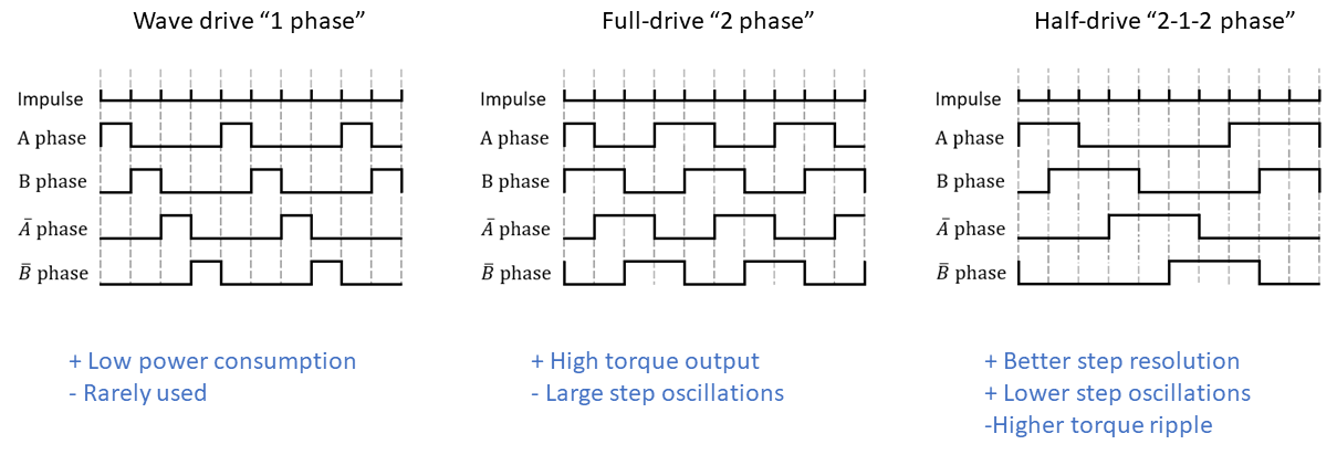
2.1 Wave "1 phase" drive
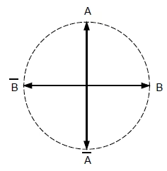
Consider a scenario where we employ just one coil to drive the stepper motor, akin to what’s depicted in Figure 1. In this mode, we only have 4 steps for a full rotation. Using a single coil does mean that the torque is quite low. Figure 4 shows the current vectors of the wave drive mode. Given that they all reside on the unit circle, theoretically, the torque strengths should be equal.
This mode involves energizing A, followed by B, then v, and finally B̅ in a repeating sequence. This straightforward sequence is easy to program.
2.2 Full-step "2 phase" drive
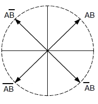
To gain more torque, we can use the full drive mode. As is clear from Figure 5, we are using two coils at the same time; e.g. coils A and B are energized, and the permanent magnet’s south pole is now between the two north poles of A and B.
However, you do not gain anymore steps per electrical cycle. All you do is shifting your pattern by 45 electrical degrees.
2.3 Half-step "2-1-2 phase" drive
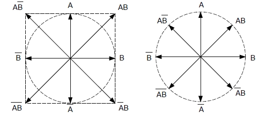
This mode is a combination of the previous two, where it jumps between the 1 phase and 2 phases modes. And those two electrical patterns are now basically laid on top of each other, creating a half-step pattern. You will also notice that having 2 phases turned on, gives more torque compared to 1 phase turned on. That is why the 2 phase current vectors are longer. Jumping between these two creates a torque ripple on your motor which can stimulate the resonance frequency inside your motor.
To get around it, you could employ current modulation techniques, such as PWM, so that when both phases are on, it can reduce the current vector back to the unit vector, as is shown in Figure 6 (right). This will increase its performance.
2.4 Microstepping
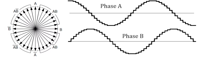
The following mode continues on the current modulation technique that is employed in the system. If you are able to use a combination of two phases with different currents, you can continue increasing the steps further. Certain stepper motors can now create 256 steps using this technique. Figure 7 (right) shows the incremental values of phase A and phase B to create these large number of steps. These microsteps are spread out over the normal 1 step of the system. The amount of energy related to a large 1-step (see Figure 1), will cause it to overshoot and create a ringing effect that might be unwanted. This can be negated with microsteps.
However, you may think that with microstepping, you can gain positional accuracy. However, that is only in the ideal case without a load. It might in some cases not be that much more accurate, but you do gain other advantages, such as lower noise of the motor itself.
2.5 Overview Modes
Figure 8 gives an overview of the different driving modes; it also serves as an indication on how to program them. For each waveform, the pros and cons are listed below the diagram.
3. Three Types of Stepper Motors
Now that we know the different modes, we take a look at the three types of stepper motors. We have the permanent magnet, the variable reluctant and the hybrid synchronous stepper motors. An illustration of all three is shown in Figure 9. The first one has already been discussed in the introduction, the other two will be discussed down below. Our main focus in this chapter is the hybrid synchronous type, as it is becoming more and more the main type you will use in your systems.
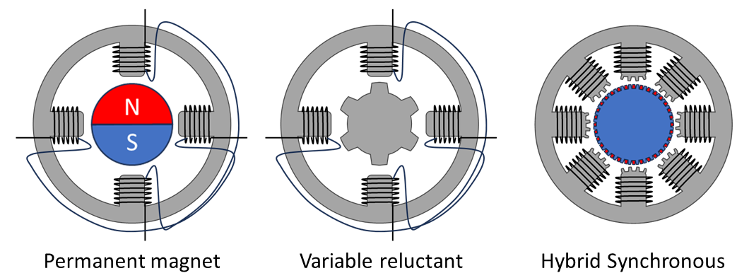
3.1 Variable reluctant
In a variable reluctance stepper motor, a significant difference is observed in the composition of the rotor. Unlike its counterparts, the rotor of a variable reluctance motor is constructed from soft iron and deliberately remains demagnetized. This unique feature plays an important role in its operation.
To illustrate, consider Figure 10 where we can observe the two opposing coils depicted in distinct colors, red and blue, representing the north and south poles respectively. In this design, both coils work in tandem, generating magnetic fields with opposite polarities. This crucial configuration facilitates the controlled movement of the rotor in precise increments.

The magnetic flux lines created by the north and south pole of the stator flow through the rotor, shown by the orange dashed line. Note that the other teeth of the rotor are not aligned with the coils of the stator that are de-energized. Figure 10 (b) shows what happens when you energize the next set of stators; the rotor will move clockwise. This can only happen because that teeth of the rotor is closest to the energized stator. With the same step process, we can continue moving the rotor as is shown in Figure 10 (c). Increasing the amount of teeth of the rotor will lead to more steps and a finer resolution.
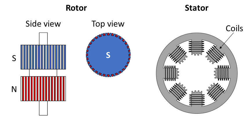
4.1 Hybrid synchronous
The hybrid synchronous stepper motor is a combination of the permanent magnet, and the variable reluctant stepper motors. The rotor is a permanent magnet, but its poles are along the axial direction, parallel to the shaft as is illustrated in Figure 11. The two poles could have 200 teeth each on them, similar idea to the teeth of variable reluctant type. The teeth of the south pole and the north pole are misaligned, as can be best seen from the top view of the rotor, where the blue color indicates the south pole. In between the gap of the teeth, you will obsere the teeth of the opposite polarity. The stator also has teeth, but with a different number. Because of this difference, the teeth of the stator and the teeth of the rotor are not all able to align.
The angular accuracy of a stepper motor is determined by the number of steps per revolution and the mechanical design of the motor. With 200 steps, and a full rotation of 360 degree, you can obtain an angular accuracy of 1.8 degrees per step.
4.1.1 Full-step drive
In Figure 13, we employ a full-step drive in the top row, where the A phases (or coils) have a north polarity, while the A̅ phases possess a south polarity. This configuration leads to an alignment between the rotor and stator along the horizontal axis. Consequently, the north pole teeth of the stator are drawn towards the south pole teeth of the rotor. Simultaneously, along the vertical axis, there is a perfect repulsion between the south poles of both the rotor and stator. This results in one axis exhibiting perfect alignment due to attraction, and another axis displaying perfect misalignment caused by the repulsion of the poles, as illustrated in Step 1.
If we proceed to deactivate phase A and activate phase B (as shown in Step 2), we observe a counterclockwise shift of the axes by 45 degrees. Now, the axis in alignment is positioned between the B poles, while the misaligned axis corresponds to the B̅ poles. This marks one complete step in the operation of the stepper motor. By commutating the current from coil A to coil B, it results in a precise 1.8 degrees of rotational movement.
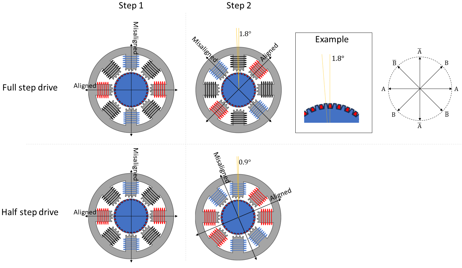
4.1.2 Half-step drive
To achieve finer movement, we can employ the Half-step drive technique, as detailed in Chapter 2.3. Starting with the initial step depicted in the bottom row of Figure 13, when transitioning to the second step, instead of deactivating coils A and activating B, we maintain A’s activation. This adjustment causes the axes to rotate by only 22.5 degrees, resulting in a step size of 0.9 degrees. By rapidly alternating between full-step and half-step modes, we can efficiently rotate the shaft.
Furthermore, it’s possible to enhance precision even further through a process of microstepping, allowing for divisions down to 1/256 steps. This yields a total of 256 × 200 = 51,200 steps for a complete rotation.
4. Interface Stepper Motor with Microcontroller
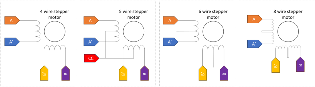
It is not uncommon to find stepper motors with 4, 5, 6 or 8 wires; nor is it always clear if it is unipolar or bipolar motor. In this section, we try to shed some light to this matter and we discuss how to connect your stepper motor to a PIC microcontroller (or Arduino).
Bipolar and unipolar stepper motors are two common types of stepper motors, and they differ primarily in the way they are wired and the complexity of the drive circuitry. The goal of this circuitry is that you want to be able to energize the coils by flowing current through it in both directions. Using the pins of a microcontroller will not suffice, and a transistor is required to get the right amount of current. A single transistor can act as a switch, but is not able to change the direction of the current. Normally, a unipolar stepper motor has a center tap in each of the windings connected to a positive voltage, while the outer ends of the coil are connected to ground through transistors. This way you are able to let the current flow left or right through the coil, but with only half a winding, it has half its strength. Bipolar on the other hand, have only one winding per phase, and require more complex circuitry, such as an H-bridge, to reverse the current direction in the winding.
Stepper motors with 5, 6 and 8 wires can be converted into unipolar motors by using a center tap; while stepper motors with 4, 6 and 8 wires can be converted into bipolar motors, as shown in Figure 14. Note that for 6 wires, you leave the center taps disconnected; and for 8 wires, you combine two coils into a single coil. Do check the datasheet of your motor to see the connections of the wire, and if it is a unipolar or a bipolar stepper motor.
4.1 Unipolar vs Bipolar
To interface a stepper motor with the PIC16F877A, you will need additional circuitry, as the pins do not provide enough current. A standard option is the ULN2003 “Array of 7 darlington transistor pairs” for driving the unipolar stepper motor, or the L293D “Quadruple Half-H drivers” for the bipolar stepper motor. See my earlier post, for the workings of the H-bridge here.
4.1.1 Unipolar Stepper Motors
The unipolar stepper motor features a common center in both windings, as depicted in the “5 wires” configuration shown in Figure 14. Given that the pins of the PIC16F877A do not supply sufficient current to drive the motor, we employ the ULN2003, which incorporates 7 darlington transistors. Since the center tap is at 5V, energizing the coil is achieved by pulling one of the other windings LOW. To set the motor in motion, it is essential to activate and deactivate each winding in a specific sequence, as illustrated in Figure 8. Please take note that in this figure, a HIGH signal indicates energizing that particular coil. It’s important to understand that in this context, energizing a coil entails pulling it to ground, which can be done by “activating” the corresponding darlington transistor pair by applying a positive voltage on the input. To conclude, to energize coil A, the corresponding pin on the MCU has to be set to HIGH. Figure 15 shows a typical circuitry with a PIC16F877A and an ULN2003. The colors are references to Figure 14, with the 5 wire scheme.
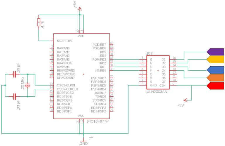
It’s important to note that if the stepper motor requires more than 5V, you will need to use a separate power supply with a voltage different from what you’re using to power the microcontroller. However, the ULN2003 driver will require the same voltage as the motor, specifically on the CD+ pin (number 9).
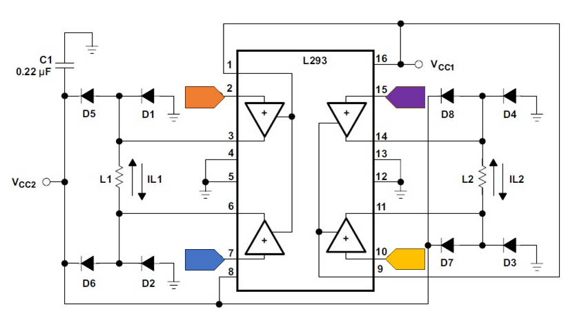
4.1.2 Bipolar Stepper Motors
In this example, we will examine the 4-wire stepper motor, which, in contrast to the unipolar type, does not have a center tap. Reversing the current requires additional circuitry, such as an H-bridge. Additionally, the datasheet specifies a few additional requirements:
- Install 8 flyback diodes to provide a path for the inductive energy generated by the motor’s coils when it is turned off. These diodes effectively create a loop for this energy to circulate, preventing any harmful voltage spikes.
- Either use a heat sink or provide enough copper area (e.g., the ground) to dissipate the heat away from the driver.
- Bypass capacitors of 0.1μF or higher need to be placed on VCC1 and VCC2 pins.
Keep in mind that the L293D component is versatile and can be used with a variety of different stepper motors. The input voltage (VCC1) is designed for microcontrollers, ranging from 4.5V to 7V. The output voltage (VCC2) has a range from VCC1 to 36V. Furthermore, the high- and low-level input voltages are compatible with both CMOS and TTL logic levels, making it compatible with almost all microcontrollers. Figure 16 depicts the circuitry of the L293D, and the table illustrates the pin mapping between the microcontroller and the L293D component.
| PIC 16F877A pin# | L293D pin# |
|---|---|
INT/RB0 |
2 |
RB1 |
7 |
RB2 |
10 |
PGM/RB3 |
15 |
5. Programming code example
Lorem ipsum dolor sit amet, consectetur adipiscing elit. Ut elit tellus, luctus nec ullamcorper mattis, pulvinar dapibus leo.
					#include <pic16f877a.h>
#include <xc.h>

// Define the frequency of the external crystal oscillator
#define _XTAL_FREQ 20000000  // 20MHz external crystal oscillator frequency

void initialize_stepper_motor() {
    TRISB0 = 0;
    TRISB1 = 0;
    TRISB2 = 0;
    TRISB3 = 0;

    PORTB = 0; // Set initial state to 0000
}

void step(int steps, int direction) {
    for (int j = 0, i = 0; j < steps; j++) {
        if (direction == 1) {
            PORTB = (1 << i);
        } else {
            PORTB = (8 >> i);
        }
        i++;
        __delay_ms(50);
        if (i == 4) i = 0;
    }
}

int main() {
    initialize_stepper_motor();

    while(1) {
        // Go clockwise for 50 steps
        step(50, 1);

        __delay_ms(1000); // Delay between rotations

        // Go counter-clockwise for 50 steps
        step(50, 0);

        __delay_ms(1000); // Delay between rotations
    }

    return 0;
}
6. Summary
This article presented an understanding of what stepper motors are. We explained the different operation modes and the three main types of stepper motors, with specific focus on the hybrif synchronous one. Lastly, we have seen how to interface them with microcontrollers and we have given a code example. For more information, I have linked several links below.
Sources
Florius
Hi, welcome to my website. I am writing about my previous studies, work & research related topics and other interests. I hope you enjoy reading it and that you learned something new.
More Posts