
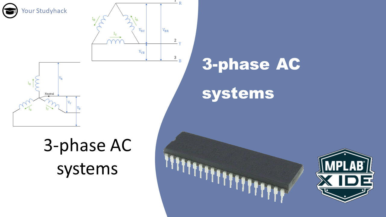
3 phase AC systems
In this article we take a closer look at the three phase power system. I will begin with giving you an overview of the differences between the two types of systems, namely the star connection and the delta connection. The sebsequent two sections will go more in-depth into the equations, ...
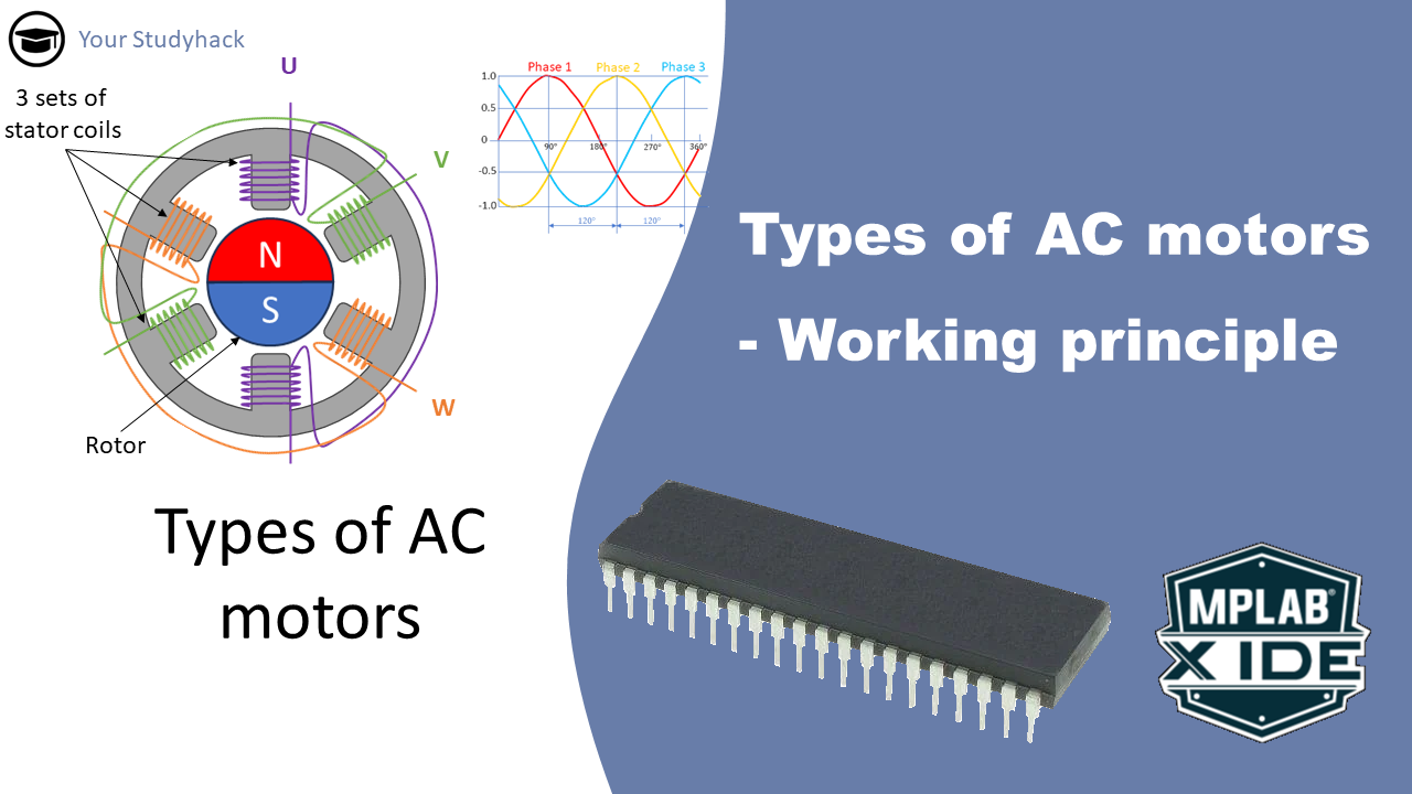
Types of AC Motors – Working Principles
Motors are primarily categorized as either AC or DC, with further classifcation based on their inherent rotation characteristics. In this article, we will commence by explaining the operation of the induction AC motor. The subsequent section delves into another type, specifically the synchronous AC motor. Finally we will provide an ...
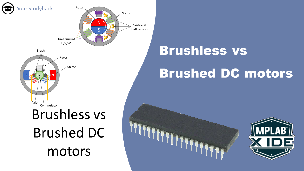
Brushless Vs Brushed DC Motors: Which to choose
Motors are primarily categorized as either AC or DC, with further classification based on their inherent rotation characteristics. In this article, we will commence by explaining the operation of the brushed DC motor. The subsequent section delves into another type, specifically the brushless DC motor. Finally, we will provide an ...
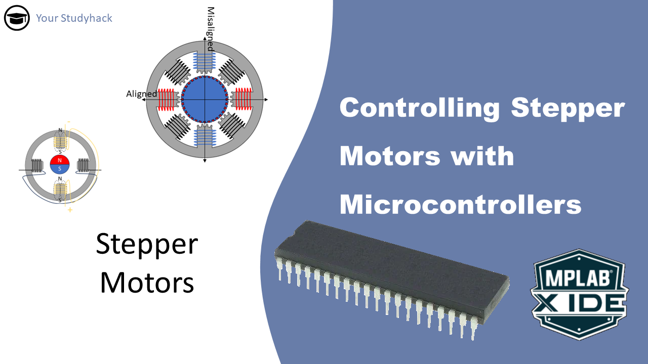
Controlling Stepper Motors with Microcontrollers
The basic principle behind a motor lies in the conversion of electrical energy into rotational mechanical movement. This can manifest as either continuous or step-wise rotation, allowing for precise control. In this context, the stepper motor stands out for its ability to stop at any given position and maintain it.
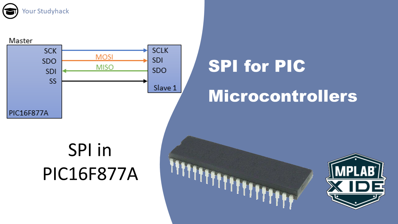
SPI for microcontrollers
In this article we will take a closer look at Serial Peripheral Interface, also called SPI. This is the third and last serial communication module in the PIC16F877A. Previously we have seen UART and I2C, and we discussed how those modules operate. Here we focus solely on SPI; what it ...
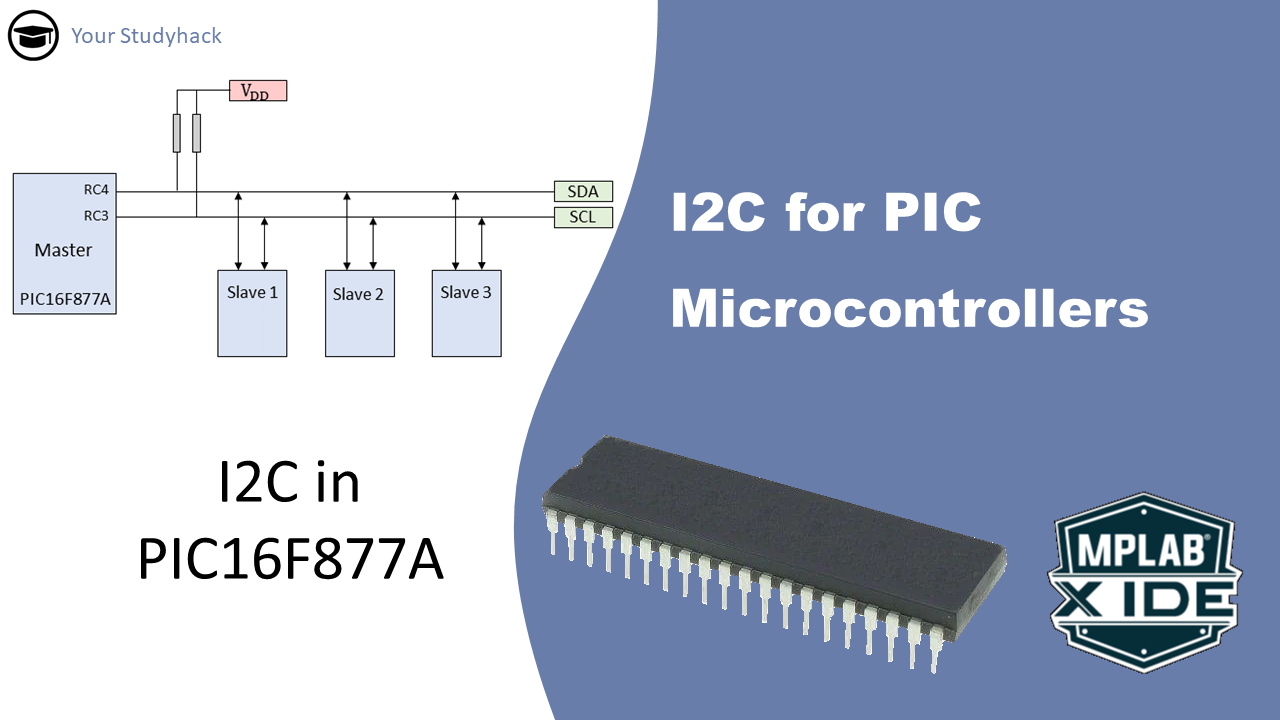
I2C for PIC Microcontrollers
In this article, we will take a closer look at the I2C serial communication protocol. This is the second in a series of three articles covering serial communication; the others focus on USART and SPI. In this post we will explain what I2C is, how it functions, and how you ...
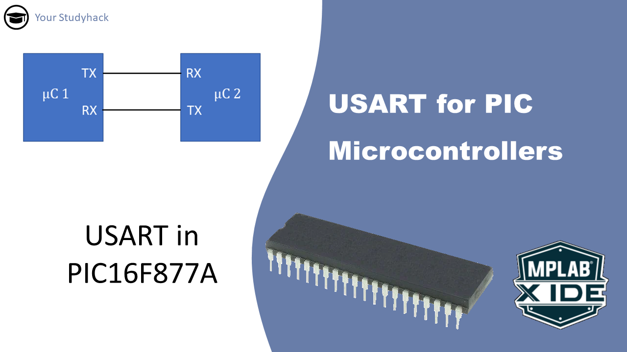
USART for PIC Microcontrollers
The USART module, also referred to as the Serial Communications Interface (SCI), is a crucial hardware module that enables a microcontroller to communicate with other devices via serial communication. This mode of communication transmits data one bit at a time.
In this tutorial, we will discuss the two different modes of ...
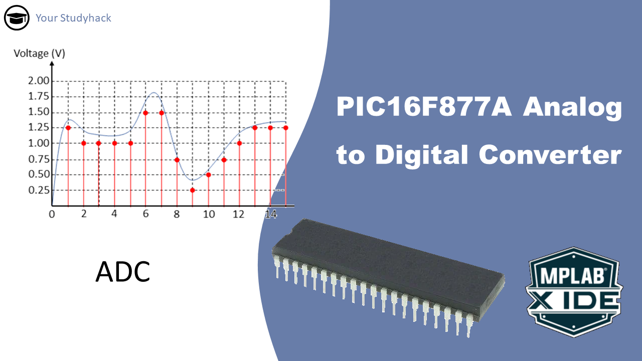
PIC16F877A Analog to Digital Converter (ADC)
The ADC module in microcontrollers indeed allows them to interface with the analog world by converting continuous analog signals into discrete digital values. This capability is crucial for various applications such as sensing, control systems, and communication. It is distinct from PWM (Pulse Width Modulation), which uses discrete pulses to ...
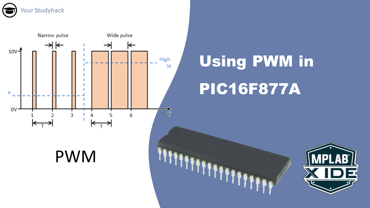
Using PWM in PIC16F877A
Digital signals (0 or 1) and analog signals (range of values) are both used in electronics. Analog inputs can be converted to digital through an ADC. To control analog devices with a microcontroller, DACs are used but they're costly and space-consuming. PWM (Pulse Width Modulation) is a cost-effective technique that ...
PIC16F877A Timer2 tutorial
The Timer2 module is an 8-bit timer/counter within most PIC MCU devices. Timer2 can increment up to a value of 255 before it overflows back to zero. Timer2 has other built-in features that make it very useful for many different applications.