Most microcontrollers have limited current sink or current source on their pins, including the PIC16F877A. However, certain projects may require larger currents than the maximum current source of 25mA for this microcontroller. As discussed in the previous two parts of this series, Bipolar Junction Transistors and MOSFETs can be used as switches. In this final part of the series, we will explore additional options for driving loads and isolating the system from the microcontroller and how we can control this. We will start by looking at one of the oldest electronic components, the relay; an optocoupler that can completely isolate one system from the other; and finally H-bridges that enables bidirectional control of DC motors.
1. Relays
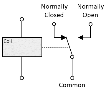
An electromechanical relay switch is a device that uses an electromagnetic coil to control the opening and closing of one or more electrical contacts. When the coil is energized, it generates a magnetic field that causes the contacts to move, either making or breaking an electrical connection. In an electromechanical relay, “NO” stands for Normally Open, “NC” stands for Normally Closed, and “C” stands for Common. These refer to the different terminal states of the relay’s contacts. In the “NO” position, the contacts are open when the relay coil is not energized. In the “NC” position, the contacts are closed when the relay coil is not energized. The “C” terminal is the common connection point for the relay’s contacts.
1.1 Microcontroller relay switch circuit
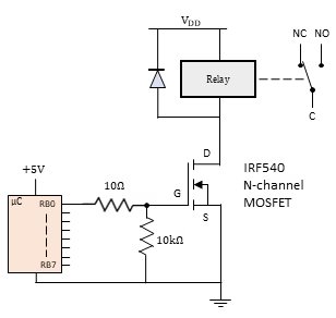
While it’s possible to connect a relay directly to a microcontroller, using a transistor as an interface between the microcontroller and the relay is often a good practice, especially for larger loads or to enhance isolation and protection. As we’ve seen in parts 1 and 2, transistors can be used as switches. Therefore, they have the capability to control the state of a relay, enabling the relay to turn on and off. This relay action, in turn, facilitates the control of larger electrical loads. One such an example is shown in Figure 2; here we use an N-channel MOSFET to turn the relay on or off.
Using a relay does not inherently provide isolation between both sides. ‘Bad grounding‘ can arise when a microcontroller shares the same ground as the system controlled by a relay switch. This can lead to problems such as electromagnetic interference, voltage spikes, ground loops, and inaccuracies in reference voltages. To mitigate these issues, it’s crucial to implement proper grounding practices. This includes establishing a single grounding point, isolating digital and analog grounds, and maintaining a clean and stable ground reference for both the microcontroller and the switched system. Employing systems such as optocouplers can help grounding issues, this is what we will discuss in the next section.
2. Optocouplers
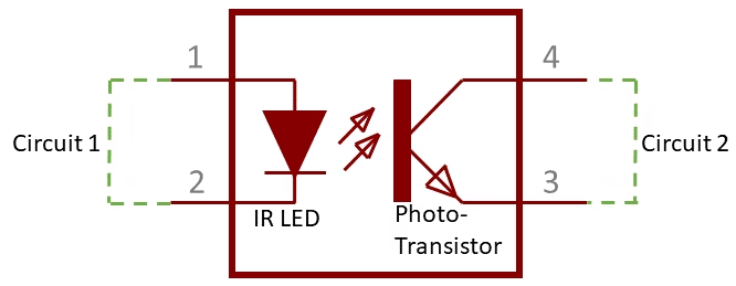
Optocouplers, also known as optoisolators, are electronic components designed to provide electrical isolation between two parts of a circuit using light. They consist of an LED (light-emitting diode) on one side and a phototransistor or photodetector on the other side. When the LED is illuminated by an electrical signal, it generates light that activates the phototransistor, allowing the transfer of information without direct electrical contact. Optocouplers are commonly used to isolate and protect sensitive components from electrical noise, voltage spikes, and interference, making them valuable for enhancing circuit safety and reliability.
Increasing the current supplied to drive the infrared LED results in a proportional increase in the current flowing through the phototransistor collector. This phenomenon is referred to as the current transfer ratio (CTR). A CTR of 100% signifies that the entire current passing through the infrared LED is conveyed 100% to the phototransistor collector.
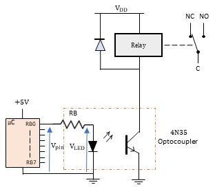
2.1 Optocoupler relay switch circuit
In the example below, we have two systems without an electrical connection between the left and right circuits. This isolation is only provided by the infrared light. The idea is to make a current flow in the circuit on the left to make the infrared LED emit light and the photo transistor in the right circuit is triggered. The calculation for the resistor RB is done in a similar fashion as how the current limiting resistor was calculated for regular LEDs. In this example we use the 4N35, with an infrared LED that requires a current of 15 mA, the forward voltage is 2V, and it has a CTR of 100%; we can use the following equation to calculate RB:
\[ RB = \frac{(V_{PORT} – V_{LED})}{I_B} = \frac{4.2-2}{0.015} = 146.66 \Omega\]
In this case, an 150 Ohm resist would suffice. As for the wattage, we can calculate it the following way:
\[P = (V_{PORT}-V_{LED})\times I_B = (4.2-2)\times 0.015 = 0.033 W\]
A typical 0.25 W resistance would be enough in this case.
With CTR of 100%, we can only give an output of the photo-transistor, similar to what we have on the input of the LED, in this case 15 mA. This might not always be enough to drive whatever load you have running. There are other optocouplers, such as the 4N45, that have a CTR of 350%.
3. Controlling motor direction & H-Bridges
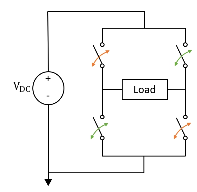
In the preceding parts (Part 1 and Part 2), we delved into the functionality of BJTs and MOSFETs, exploring how they can be harnessed to manage loads, including motors. Yet, a solitary transistor offers control in just one direction. In numerous applications, the necessity arises for bidirectional control, akin to steering a car. For such scenarios, a more intricate arrangement of transistors emerges — the H-bridge. This network empowers the manipulation of current flow and motor direction, enabling seamless control in forward and reverse motions. Figure 5 shows a representation of the H-bridge with switches. These switches have to be turned on and off in a specific fashion to make the current flow through the load without shorting the circuit.
3.1 BJT H-bridge example
Within this animation, you’ll observe four distinctive states attainable through pins A and B. The BJTs are configured and calculated as explained in Part 1 of this series. Let’s delve into the exploration of these four states, which can be achieved by applying logic 0 or logic 1 to the input gates. While ensuring the absence of a direct route from VCC to ground, as such a path can lead to detrimental effects on the transistors.
_A low_ and _B low_: When both inputs are set to logic 0, solely the upper two PNP transistors become active. Given their simultaneous activation, no current is permitted to traverse the ground, resulting in a state of inactivity.
_A high_ and _B low_: By elevating A to a high state, the left-side NPN transistor becomes active. Correspondingly, pulling B low activates the right-side PNP transistor. This configuration establishes a channel through which current can flow from the right to the left, controlling the motor in that direction.
_A low_ and _B high_: Similarly, with the NPN transistor on the B side and the PNP on the A side activated, current courses from left to right within the motor, causing it to move in the opposite direction.
_A high_ and _B high_: In this scenario, both NPN transistors engage, yet no power supply is available to energize the motor. Consequently, the motor remains deactivated.
Across all four cases, no direct path for current from VCC to ground is available, demonstrating the H-bridge’s prowess in enabling bidirectional motor control.
3.2 Challenges with H-bridges
Although an H-bridge can help resolve certain issues, you may encounter challenges during its implementation. In this section, I aim to provide assistance in overcoming these challenges and offer guidance on areas that require heightened attention.
- In modern H-bridge circuit designs, particularly those involving voltages exceeding 9V, the utilization of Bipolar Junction Transistors (BJTs) is infrequent. Instead, MOSFETs have become the preferred choice due to their heightened efficiency in high-voltage scenarios, leading to diminished power dissipation compared to conventional BJTs. These types of H-bridges closely resemble the configurations I’ve previously illustrated, where the BJT is substituted with a MOSFET. It’s important to note that when transitioning from PNP BJTs to P-channel MOSFETs, pull-up resistors are necessary (connected to the microcontroller’s VCC) to ensure that logic 1 corresponds to 5V (Pull-down resistors are required for the N-channel MOSFETs). You can keep the in-series resistor between the gate and microcontroller, consider reducing its value to a range of 10 Ohms to 100 Ohms.
- Always include diodes to manage the back-EMF generated by inductive loads, as neglecting this precaution can result in circuit damage.
- H-bridges have the potential to introduce high-frequency noise into the system, which can interfere with the microcontroller’s operation. Effectively addressing this issue requires the proper isolation techniques, such as employing an optocoupler as discussed in the previous section.
- When a high switching frequency is necessary, it’s essential to understand that PNP and NPN BJTs, as well as N-channel and P-channel MOSFETs, exhibit differing switching times. These variations are attributed to the majority carriers (electrons or holes) responsible for current flow.
- Controlling the speed of the wheels can be achieved through a technique called PWM; by putting a duty cycle between 0% and 100%, the average voltage delivered to the motor can be varied, allowing for precise control of the motor’s speed.
3.3 H-bridge interfaced with PIC16F877A
After gaining a thorough understanding of the H-bridge, coding should not present the most challenging obstacle. Below you’ll find a basic code that cycles through all four states in a loop, each separated by a 1 second delay. Depending on your specific project, it is recommended to tailor the code accordingly.
					#include <xc.h>

// Configuration bits
#pragma config FOSC = HS   // External crystal oscillator
#pragma config WDTE = OFF  // Disable Watchdog Timer
#pragma config PWRTE = OFF // Disable Power-up Timer
#pragma config BOREN = OFF // Disable Brown-out Reset
#pragma config LVP = OFF   // Disable Low Voltage Programming

#define _XTAL_FREQ 20000000  // Define the external crystal frequency

void main() {
    TRISB = 0x00;  // Set PORTB as output
    TRISB6 = 0;    // Set RB6 as output connected to A
    TRISB7 = 0;    // Set RB7 as output connected to B

    while(1) {
        // A and B both 0, do nothing
        RB6 = 0;
        RB7 = 0;
        __delay_ms(1000);

        // A and B both 1, do nothing
        RB6 = 1;
        RB7 = 1;
        __delay_ms(1000);

        // A is 1 and B is 0, drive motor one direction
        RB6 = 1;
        RB7 = 0;
        __delay_ms(1000); // Delay for motor movement

        // B is 1 and A is 0, drive motor other direction
        RB6 = 0;
        RB7 = 1;
        __delay_ms(1000); // Delay for motor movement
    }
}
4. Common types of relays, optocouplers and H-bridges
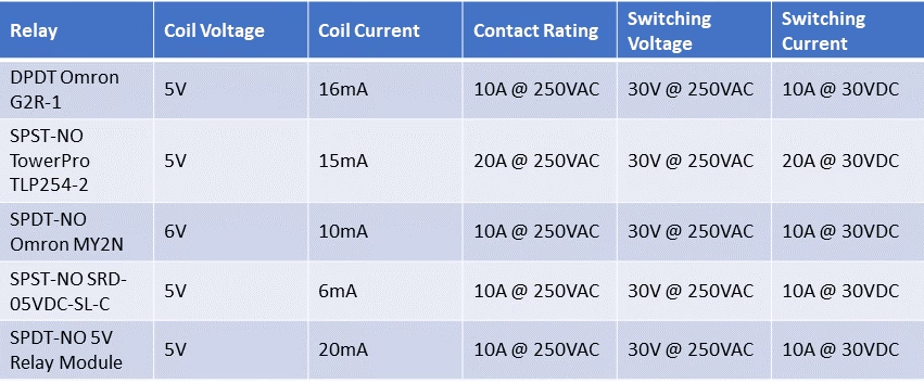
- The coil voltage and current. These must be compatible with the power supply that you will be using.
- The contact rating. This is the maximum current and voltage that the relay can switch.
- The switching voltage and current. This is the voltage and current that the relay can switch between its contacts.
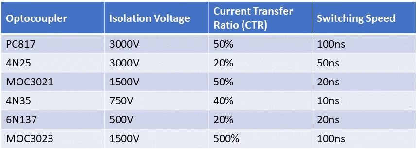
- The isolation voltage. This is the maximum voltage that can be applied between the input and output terminals of the optocoupler without causing breakdown.
- The current transfer ratio (CTR). This is the ratio of the output current to the input current. A higher CTR means that the optocoupler will provide a stronger output signal.
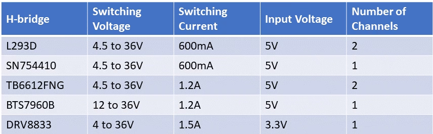
- The switching voltage. This is the maximum voltage that the H-bridge can switch.
- The switching current. This is the maximum current that the H-bridge can switch.
- The input voltage. This is the voltage that is required to power the H-bridge’s control circuitry.
- The number of channels. This is the number of motors that the H-bridge can control.
Florius
Hi, welcome to my website. I am writing about my previous studies, work & research related topics and other interests. I hope you enjoy reading it and that you learned something new.
More Posts