1. Introduction to Ferromagnetism
Magnetism is the force that is exerted by magnets when they repel or attract each other. It is caused by the motion of electric charges. Electrons can spin like tops, and they orbit around the nucleus of the atom. You could image this orbit as a circle, and it generates an electric current, that causes the electron to behave like a microscopic magnet.
If the direction of the spin is random, averaged over the total sample, it will cancel out their magnetism. In other materials, the electron spin can align, and will therefore be strongly magnetic. All materials have some type of magnetism, and we can classify these according to their bulk susceptibility, (χ), which is the measure of how much material will become magnetized in an applied magnetic field. The different types are:
- Diamagnetic materials, such as paper and cloth;
- Paramagnetic materials, such as aluminium and oxygen;
- Ferromagnetic materials, such as iron, cobalt or nickel;
- Ferrimagnetic materials, such as Yttrium Iron Garnet (YIG) and magnetite, and;
- Antiferromagnetic materials, such as MnF2 and α-hematite.
The force of a magnet on diamagnetic, paramagnetic, and antiferromagnetic materials is normally so weak, it can only be detected by laboratory instruments. In this article, I will focus mainly on the most familair one, the ferromagnet.
Talk about usage of ferrromagnets (magnetic storage), talk about soft and hard magnets, and then talk about hysteresis.
1.1 Hard and Soft Magnets
The strength of the magnetic field needed to align the magnetic domains classifies the ferromagnetic material as a hard or soft magnet. This property is expressed in the coercivity, Hc. Hard magnets have a large Hc, and retain their magnetization even in the absence of an applied field, while soft magnets have a low value of Hc.
A great example of a hard magnet, is magnetic storage material. Here we want to induce a large permanent magnetization by an external field (the writing head), so that it stays intact for 20+ years. It should be strong enough to produce a measurable effect when the reading head is on top. But it shouldn’t be too strong, because if it needs to be overwritten, it might have to change. This can be seen at the large reversed field that is required to get to the opposite magnetization.
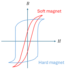
Transformer cores are a good example of soft magnets. This ferromagnetic material transports a large magnetic flux B produced by the primary coil to the secondary coil. To obtain a good transformation, you want the induced flux B to follow the primary field H as closely as possible.
Ideally, you want no hysteresis loop at all, but rather just a straight line. But in the real soft magnet, there is going to be a little bit of magnetization left. So that B will follow H rather closely. The smaller the area enclosed by the hysteresis loop is, the lower the energy losses. As the area within this loop represents the energy dissipated as heat in the material during one complete cycle of magnetization and demagnetization.
1.2 Hysteresis loop
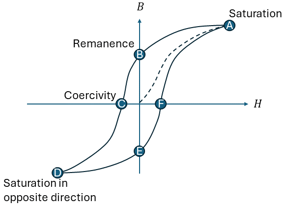
A hysteresis loop, as illustrated in Figure 2, shows the relationship between the induced magnetic flux density (B) and the magnetizing force H). It is also called the B-H loop. You obtain it by measuring the magnetic flux of the ferromagnetic material while you change the magnetizing force. If a material has never been magnetized before (or has been demagnetized by having its temperature above the Curie temperature), it will start at the origin and follows the dashed line as H is increased. The greater the amount of magnetizing force, the stronger the magnetic field in the component. At point ‘a’, almost all the magnetic domains have aligned, and any increase in H will produce very little change in B. At this point, it has reached its magnetic saturation.
Lowering H to zero, will move the curve from ‘a’ to point ‘b’. You can see that a certain magnetic flux remains in the material, even without a magnetizing force. This is called the remanence point, where some of the magnetic domains remain aligned, and some have lost their alignment. Reversing the magnetizing force, moves the curve to point ‘c’, where the magnetic flux is brought down to zero. This is the point of coercivity (Hc), where enough domains have flipped to have a net flux of zero.
Increasing the magnetizing force in the negative direction brings the material again into its magnetic saturation, but in the opposite direction (point ‘d’). From here we can increase the magnetizing force again to zero, at point ‘e’, and increasing H further in the positive direction will return B to zero, in point ‘f’. As you might notice, it does not return to the center, but will take a different path, as some extra force is now required to remove all the residual magnetism.
1.3 Magnetic domains
At the atomic scale, spins of ferromagnetic materials are aligned and parallel. However, at the macroscopic scale, not all the spins are necessarily aligned, due to the formation of magnetic domains, which all have different orientations for the magnetizations (M). Inside each domain the magnetization is uniform. However, the relative orientation of M varies from domain to domain. When an external magnetic field H is applied to the material, all the domains tend to orientM parallel to H, to reduce the energy of the system:
\[E_H = -\mu_B\textbf{M}\cdot\textbf{H} = -\mu_B\textbf{MH}\textrm{cos}(\theta)\]
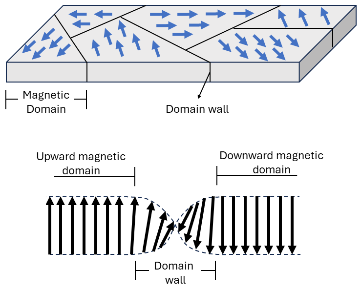
The formation of domains does have some energy cost. The exchange interaction in a ferromagnet aligns spins because that reduces the total energy of the system. At a domain wall (the boundary between two domains), perfect ferromagnetic alignment clearly cannot hold, and therefore the local energy will be higher. However, domain formation can be favored if that exchange cost is balanced by a net savings in stray field energy.
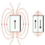
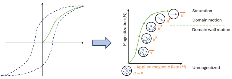
Figure 5 shows a schematic illustration of the change of magnetic domains from an initial condition at zero magnetic field to saturation. Domains with an aligned magnetic moment grow at the expense of the poorly aligned ones to lower the total energy. Increasing the applied magnetic field, will start to rotate the domains that have a different orientation. This causes the domain wall to move, effectively creating a larger single domain. At the saturation field, all the domains have aligned into a single domain, which is aligned to the applied field.
There are multiple ways to visualize the domain walls in (anti-)ferrmagnetic materials. One way, is the magneto-optic Kerr effect (MOKE), which uses the rotation of the polarization of light reflected from a magnetic surface. Another technique is the Magnetic Force Microscopy (MFM), which is similar to atomic force microscopy, but with a magnetically coated probe tip that samples the surface. There also exist numerical visualization methods that can be used to help as well.These fall under micromagnetics, and there are several great options.
2. Fundamental concepts and atomic magnetic moments
The differences in magnetic properties are manifestations of the magnetic state of the atoms of the material. The following is a brief explanation of the magnetism of atoms. A certain degree of quantum theory is probably required to accurately understand it.
2.1 Orbital Angular Momentum
In quantum mechanics, the orbital angular momentum of an electron, L, arises due to its motion around the nucleus. It is a quantized vector quantity, meaning its magnitude and direction take on specific discrete values.
The magnitude of the orbital angular momentum is given by:
\[|\textrm{L}|=\sqrt{l(l+1)}\hbar\]
where l is the orbital quantum number and can take on integer values 0, 1, 2, …, n-1. Here, n is the principal quantum number which indicates the energy level or shell of the electron.
In the presence of a magnetic field, the component of the orbital angular momentum along the direction of the field (chosen as the z-axis) is also quantized:
\[\textrm{L}_z = m_l\hbar\]
where ml is the magnetic quantum number and can take values from -l to +l in integer steps.
2.1.1 Magnetic Moment (Orbital)
The motion of an electron around the nucleus not only results in angular momentum but also generates a magnetic dipole moment. This magnetic moment, μL, is directly related to the orbital angular momentum L.
Classically, for a charged particle e moving in a circular orbit with radius r and angular velocity ω, the magnetic dipole moment can be calculated as:
\[|\mu_{L}|= \text{current} \times \text{area} = (e\cdot\frac{\omega}{2\pi})(\pi r^2) = \frac{e\omega r^2}{2}\]
The angular momentum of the electron in classical terms is:
\[|\textrm{L}|=m_e\omega r^2\]
By substituting the angular velocity ω and orbital radius r from the above relation into the expression for the magnetic moment, we get:
\[|\mu_{L}|= \frac{e}{2m_e}|\textrm{L}|\]
Using the quantized expression for L, the magnetic moment becomes
\[|\mu_L| = \frac{e\hbar}{2m_e}\sqrt{l(l+1)}=\mu_B\sqrt{l(l+1)}\]
where \[\mu_B =\frac{e\hbar}{2m_e}\] is the Bohr magneton.
2.2 Spin Angular Momentum
In addition to orbital angular momentum, electrons possess an intrinsic form of angular momentum called spin angular momentum, denoted by S. Unlike orbital angular momentum, spin is an intrinsic property of particles and does not arise from any physical motion.
The magnitude of the spin angular momentum is given by:
\[|\textrm{S}| = \sqrt{s(s+1)}\hbar\]
where s is the spin quantum number. For electrons, s is always 1/2.
The component of the spin angular momentum along a chosen axis (typically the z-axis) is quantized:
\[\textrm{S}_z = m_s\hbar\]
where ms is the spin magnetic quantum number and can take the values ±1/2.
2.2.1 Magnetic Moment (Spin)
The spin of an electron generates a magnetic dipole moment, known as the spin magnetic moment (μS). This magnetic moment is given by:
\[\mu_S = -g_s\mu_B\frac{S}{\hbar}\]
where gs is the g-factor for the electron’s spin, approxiately equal to 2.002319. The negative sign indicates that the magnetic moment is antiparallel to the spin angular momentum for electrons. The magnitude of the spin magnetic moment can thus be expressed as:
\[|\mu_S| = g_s\mu_B\sqrt{\frac{3}{4}}=\mu_B\sqrt{3}\]
2.3 Total Angular Momentum
The total angular momentum J is the vector sum of L and S:
\[\textrm{J} = \textrm{L} + \textrm{S}\]
The total magnetic moment μJ is then:
\[\mu_J = g_J\mu_B\frac{\textrm{J}}{\hbar}\]
The Landé g-factor for the total angular momentum, gJ, is a complex equation, but is normally between 1 and 2. When it has more orbital angular momentum it is closer to 1, and when it has more spin angular momentum, it is closer to 2. The equation to calculate it is as follows:
\[g_J = 1+\frac{j(j+1)+s(s+1)-l(l+1)}{2j(j+1)}\]
2.4 Hund's rule
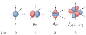
The location and energy of every electron in an atom are determined by a set of 4 quantum numbers, that describe different atomic orbitals, which is a region of probability where an electron can be found. As each orbital can only hold two electrons, the more electrons an atom has, the more orbitals it will need. There are s, p, d and f orbitals with different shapes, as shown in Figure 6.
The first quantum number is the principal quantum number n, which can have any positive integer value, n = 1, 2, 3, …. When picturing the Bohr model, it represents the energy level of the electron. The larger the number of n, the further away from the nucleus it is.
The next quantum number is the orbital momentum quantum number l, which can have any value from 0 to n-1. As an example, when an electron has an n value of 3, then l = 0, 1 or 2. When l=0, we describe the s orbitals, which are spherical and only there is only one per energy level. When l=1 we describe p orbitals, which are lobes that extend outwards on the three axes. There are three of these per energy level. When l=2, we describe the d orbitals, which have a strange shape, and there are five of them per energy level. Finally, when l=3, we describe the f orbitals, which are even more complicated. There are seven of them per energy level. Examples of each different number, are given in Figure 6.
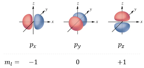
Next we have the magnetic quantum number, ml, which takes values from -l to +l. As an example, when l=2, the magnetic quantum number can be –2, -1, 0, 1, or 2. This determines how many orbitals there are of a type per energy level, and therefore describes a specific orbital amongst a particular set. Figure 7 shows when l=1 and we look at the p orbitals. In this case ml can be -1, 0, or +1, corresponding to the three different sub-orbitals, px, py and pz.
The last quantum number is the spin quantum number, ms = +1/2 or -1/2. So each electron only has 2 options for this number.
With this we have 4 quantum numbers, namely n, l, ml , ms. No two electrons in an atom can have the same quantum numbers as stated by the Pauli exclusion principle. So each orbital can only have 2 electrons, and those two electrons have opposite spin values.
2.4.1 Aufbau Principle
A large atom has to use multiple orbitals to house all the electrons. The Aufbaum principle tells us about the order in which the atom fills up the orbitals. This is determined by their relative energies, as orbitals which are further away from the nucleus have higher energies.
It starts with 1s, then 2s and then 2p and 3s, etc.
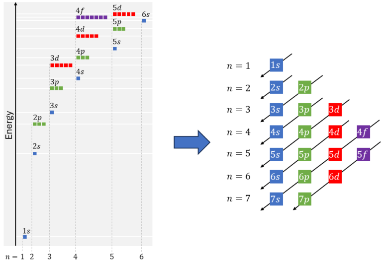
As an example, a neutral Sulfur atom has 16 electrons, meaning we require several orbitals. The way to write down the electron configuration is done with the following example: 2p6, where the 2 stands for the n-value and the upperscript 6 stands for the number of electrons. For Sulfur we need to use the following orbitals
- 1s2,
- 2s2,
- 2p6,
- 3s2,
- 3p4.
The total electron configuration for Sulfur(16) is: 1s22s22p63s23p4. A common abbreviation is to use the noble gas from the row above in the Mendeleev table, and list it in brackets; e.g. [Ne]: 1s22s22p6. Then list the valence electrons that are remaining in the following way:
\[[Ne]3s^23p^4\]

2.4.2 Orbital diagrams and hund's rule
In order to understand the magnetic properties of materials, we have to take a deeper look into the electrons spin distribution. Each electron state may be occupied by two electrons, one with spin up and one with spin down. The electron spin distribution is determined by Hund’s rule. The rule states that when there is orbital degeneracy, the electrons will be arranged to maximize the total spin. This means that we first fill up half the states, before doubling them up.
The physical origin of this rule is that two electrons with the same spin can never be found at precisely the same place. Electrons of the same spin avoid each other, and the repulsive Coulomb interaction energy between them is smaller than for electrons of opposite spin.

In case of equal number of electrons with spin up and spin down, the material is diamagnetic and the net spin magnetism is zero.
However, many materials are paramagnetic, i.e. the electron spins on each atom do not completely cancel; each atom has a net spin and a net magnetic dipole moment. Materials that have a net spin and as such a net magnetic dipole moment, typically remain only very weakly magnetic because the individual atomic magnets are uncoupled and point in random directions. If an external magnetic field is applied, the individual magnets attempt to align with this applied field. At room temperature and usual magnetic fields, the energy of an individual atomic dipole is small compared to kBT, and this leads to only a tiny paramagnetic susceptibility, that requires laboratory instruments to measure.
The interesting applications of magnetic materials tend to come not from paramagnetism or diamagnetism, but from arrangements such as ferromagnetism where the magnetic moments remain aligned even in the absence of an external magnetic field. In order to understand ferromagnetism, we need to consider not just interactions between individual magnetic moments and the external field, but also interactions between the magnetic moments.
3. Mechanisms and Models of Ferromagnetism
3.1 Exchange interaction
Exchange interaction is the main culprit behind ferromagnetism, and has no classical analog to explain. It is a quantum mechanical effect that alters how particles behave based on their indistinguishability and spin. For this, we need to understand a few key concepts:
- Indistinguishable particles: In quantum mechanics, some particles (like electrons) are considered indistinguishable, meaning you can’t tell them apart.
- Wave function: A wave function is a mathematical description of the quantum state of a particle or system of particles.
- Exchange Symmetry: This is a property of the wave function that changes when you swap two indistinguishable particles. For fermions (i.e., electrons), the wave function changes sign, while for bosons, it remains unchanged.
- Coulomb Interaction: This is the force between charged particles (like the repulsion between two electrons due to their negative charges).
The effect of the exchange symmetry is that for fermions, the electrons stay apart from each other (for bosons they get closer). This behavior is a result of the Pauli exclusion principle, which states that no two fermions can occupy the same quantum state. The exchange interaction is a combination of the exchange symmetry and the Coulomb interaction. For electrons in an electron gas, because of exchange symmetry, an “exchange hole” forms. This means that electrons with the same spin avoid each other, lowering the energy from their mutual repulsion. This decreases the energy associated with the Coulomb interactions between the electrons with same spin. This alignment of spins due to exchange interaction is a key factor in ferromagnetism, where materials exhibit a permanent magnetic field.
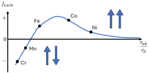
The periodic arrangement of the spins in these materials results from an electrostatic coupling between the electrons and nuclei of the neighboring atoms, called the exchange coupling:
\[U_{ex}=-2J_{ab}\textbf{S}_i\cdot\textbf{S}_j\]
where Si and Sj are the spin vectors on atoms i and j, and Jab is the exchange constant, which is a function of the Coulomb integral (i.e. the repulsive potential for electron-one in an electric field created by electron-two), the overlap integral, and the exchange integral (Jex ), which is similar to Coulomb integral but includes the exchange of the electrons. In the case of orthogonal orbitals, (i.e. with different orbitals in the same atom), than the exchange integral and exchange constant are the same; Jab = Jex.
It turns out that Jab can be positive (parallel alignment favored; ferromagnteism) or negative (anti-parallel alignment favored; antiferromagnetism). The exchange interaction is orders of magnitude stronger than the magnetic dipolar interactions and is the source of ferromagnetism. For a lot more in-depth information on the exchange interaction, with mathematical derivations, check my article on Exchange Interaction.
3.2 Hybridization
Ferromagnetism occurs when an electron system becomes spontaneously spin-polarized. In transition metals, this phenomenon results from a delicate balance between atomic-like exchange interactions, which favor spin alignment, and inter-atomic hybridization, which tends to reduce spin polarization.
In isolated atoms, Hund’s rules govern the arrangement of electrons to minimize energy. Hund’s first rule maximizes the spin by filling a partially filled orbital with electrons of the same spin before pairing spins in the opposite direction. This maximizes the atomic exchange energy by keeping electrons with the same spin further apart, reducing their Coulomb repulsion.
In solids, electrons on neighboring atoms hybridize to form bands, which can suppress magnetic moment formation. Band formation disrupts the spherical symmetry of each atom’s environment, quenching the orbital component of the magnetic moment. Additionally, creating spin polarization involves a kinetic energy cost, as electrons must move from lower-energy filled band states to higher-energy unoccupied states. Because of this, most materials are non-ferromagnetic.
Despite these inhibitions, some materials, particularly transition-metal ferromagnets like iron, cobalt, and nickel, do exhibit ferromagnetism. These materials have partially filled d-orbitals and exhibit strong exchange splitting alongside significant hybridization. The exchange splitting can stabilize a spin-polarized ferromagnetic state even with band formation, by shifting the majority-spin electron band states to lower energies than the minority-spin states. This self-consistent energy shift more than compensates for the kinetic energy cost of spin polarization, allowing these materials to maintain ferromagnetic order.
Thus, the interplay of exchange interactions and hybridization in transition metals leads to the fascinating phenomenon of ferromagnetism, where spontaneous spin polarization results in a macroscopic magnetic moment.


