1. Introduction
Berger and Slonczewski [1][2] demonstrated the theoretical feasibility of utilizing a spin-polarized current to influence local magnetization of a ferromagnet. This idea revealed the potential for inducing steady-state precession or even complete reveral of the magnetization solely through spin transfer. The method of magnetization control through electrical currents, rather than magnetic fields presented a lot of possibilities for practical applications.
Next to the charge, electrons also posses spins. In normal electronic circuits it is of (hardly) no use, as they are orientated randomly in non-ferromagnetic materials. However, when we integrate ferromagnetic components into these devices, the itinerant electrons can become partially spin polarized, with their spins taking on a more ordered configuration. The interaction between spins of electrons and ferromagnetic materials lead to spin-based effects, influencing the flow of current based on their magnetization orientation. Moreover, these interactions enable electron spins to exert influence on the orientation of magnetizations themselves. This phenomenon is termed Spin-Transfer Torque (STT).
The concept of spin-transfer torque has gotten a lot of interest and has been used in many laboratories and actual spintronic devices. Such devices include metallic/ferromagnetic multilayers (GMR effect) and magnetic tunnel junctions (TMR effect) when the spacer between the ferromagnetic material is an insulator (or semiconductor). Despite their differences, they have in common that their cross-sectional area is in the sub-micron range. This small size is crucial, as spin-transfer torque only works under very high current densities, in the order of 108 A/cm2 [3].
2. Spin-Transfer Torque
2.1 Macroscopic spin mode
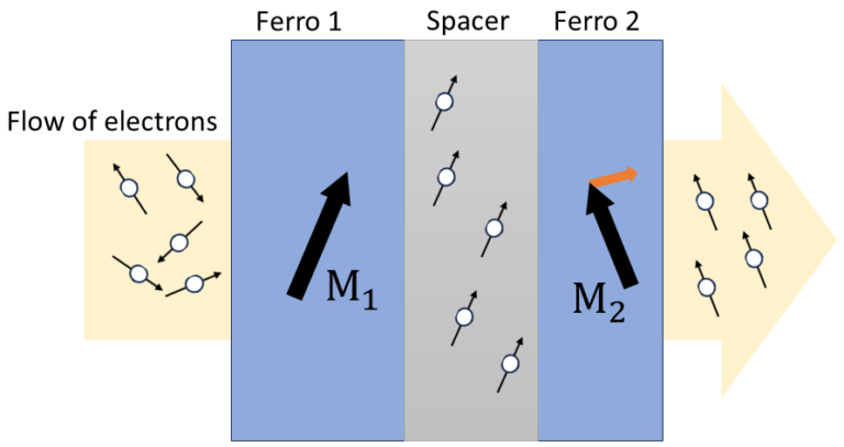
Take the model in Figure 1 as example. When a spin current is (spin-)filtered by one ferromagnetic layer, is passing through another magnetic layer, whos magnetization is not aligned with the first layer; the second magnet absorbs a portion of the spin angular momentum that is carried by the electron spins. Thus, the magnetization of the ferromagnet changes the flow of the angular momentum of the spin by exerting a torque on the spins to reorientate them. But due to conservation of momentum, the flowing electrons must also exert an equal and opposite torque on the ferromagnet. This torque from the polarized electrons onto the ferromagenet is called a spin-transfer torque.
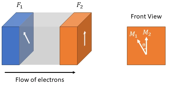
To explain the principles of STT, we start with a macrospin model, containing two ferromagnetic layers, labeled F1 and F2, separated by a spacer (this can be metallic, insulator or semiconductor) [4]. The magnetizations of the two ferromagnets are misaligned by an angle $\theta$, as shown in Figure 2. An electric current is passing through it, so that the electrons flow from F1 to F2. The electrons that flow into F1 are spin polarized along the direction of magnetization (M1), of this ferromagnetic layer. Similarly, electrons flowing through F2 are polarized along M2.
Now let’s consider an electron in the ferromagnetic layer F1 with a magnetic moment μ1 parallel to M1, and another electron in F2 with a magnetic moment μ2 parallel to M1. As they are not the same, when it is being moved through the total structure, some of this magnetic moment has to be transfered to the system per time unit. As the magnetization vector has a fixed magnitude (length), any variation in time has to be perpendicular to M. That means that only the component perpendicular to M of the magnetic moment can be transfered to the total bulk magnetization. This total transfered moment (T), is composed into two parts, T1 and T2. The part T1 is the magnetic moment μ1 that is transfered to the magnetization M1.
The μ1 that is transfered to M1 is a vector orthogonal to M1, and lies in the plane created by M1 and M2. The vector that is orthogonal to both M1 and the plane, is M1 × M2, as shown in Figure 2, by coming into the plane. Hence, T1 and T2 can be written as
\[\vec{T}_{1,2} = T_{1,2}\vec{M}_{1,2}\times(\vec{M}_1\times\vec{M}_2) \ ,\]
where T1,2 is the length of the torque, and the vector product M1,2 × (M1 × M2) creates a vector perpendicular to M1,2 to the right. This torque was dubbed by Slonczewski as “pseudo-torque”, but now goes by the name of spin-transfer torque [4].
2.2 At the microscoping level
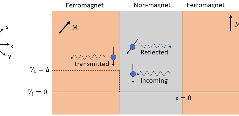
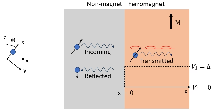
To explain it, we use a 1-dimensional model [5] of an interface between a normal metal and a ferromagnet, as illustrated in Figure 3. We assume a single spin-polarized electron moves in the x-direction, incident on a magnetic layer whose magnetization is in the z-direction. This electron has the wavefunction [6]:
\[\psi_{in} = \frac{e^{ikx}}{\sqrt{\Omega}}\left(cos(\theta /2)\mid\uparrow\rangle + sin(\theta /2)\mid\downarrow\rangle\right)\ ,\]
where Ω is a normalization volume.
We will use the Stoner-model approach to describe the ferromagnetic layer [6]. In this model, we assume that the electrons in the ferromagnet experience an exchange splitting (Δ), which moves the states of the minory-spin carrier band ∣↓⟩ to a higher energy, compared to the majority-spin carrier band, ∣↑⟩. It is further assumed that electrons move independently of one another and are not significantly influenced by the atomic cores or lattice structure of the material, thus electrons have a free-electron dispersion. Electrons scatter from the energy barrier at position x=0, which has different heights for spin-up and spin-down electrons. To make it easier, we shift everything so that for spin-up the height of the potential energy is 0, while for spin-down it is Δ, as is shown in Figure 4. They calculated, by matching wavefunctions and their derivatives at the interface (x=0), the spin current density of the transmitted and the reflected spin currents [6]:
\begin{aligned}
\textbf{Q}_{trans} & =\frac{\hbar^2}{2m\Omega} \textrm{sin}(\theta)k \textrm{cos}[(k_\uparrow -k_\downarrow) x]\vec{\textbf{x}}\\
& -\frac{\hbar^2}{2m\Omega} \textrm{sin}(\theta)k \textrm{sin}[(k_\uparrow – k_\downarrow) x]\vec{\textbf{y}}\\
& +\frac{\hbar^2}{2m\Omega} \left[k \textrm{cos}^2(\theta /2)-k_\downarrow\left(\frac{2k}{k+k_\downarrow}\right)^2 \textrm{sin}^2(\theta /2)\right]\vec{\textbf{z}}\end{aligned}
\[\textbf{Q}_{refl} = \frac{\hbar^2}{2m\Omega}k\left(\frac{k-k_\downarrow}{k+k_\downarrow}\right)^2 \textrm{sin}^2(\theta /2)\vec{\textbf{z}}\]
where Ω is a normalization volume, ℏ is the reduced planck constant, θ is the angle of the spin orientated in the x-z plane with respect to the z-direction, k is the wavevector, and describes the spatial frequency and direction of propagation of the wave. For these calculations k↑ = k and k↓ < k.
With these calculations we can observe a few interesting facts. Firstly, it shows that in the reflected spin current density, there is no transverse component (meaning no x– and y-direction). That means that all of the transverse components of the incident spin current density is being transmitted into the ferromagnet. This result follows from the fact that in the Stoner-model, the amplitude of the potential energy barrier for spin-up is zero, while for spin-down it has a finite amplitude, meaning that the reflected part is purely spin-down. Even with this simplistic model, there are many combinations of metal/ferromagnet materials where this is a reasonable approach. As an example Cu/Co, Cu/Ni, or Cr/Fe have a reflection magnitude of almost zero [7][8][6].
The second interesting fact is what happens to the transverse components (x, y) of the spin current density (Qtrans) once it is inside the ferromagnet. The oscillatory term in those components represent the precession of the spin around its z-axis as a function of its position x (how far it penetrates the ferromagnet).Because spin-up and spin-down have a difference between k↑ and k↓ , they don’t travel at the same speed. This induces a phaseshift between these them. In other words, the spin precesses around the local magnetization with very small spatial prpecession period, in the order of a few atomic spacings. That means that electrons crossing the interface from different directions, follow different paths into the ferromagnet, and the precession of all of them combined, rapidly averages to zero due to classical dephasing. Thus, within 1-2 nm, the spins that crossed the interface will have transfered their momentum to the local magnetization of the ferromagnet[6][8][9].
2.3 Reflected spin current
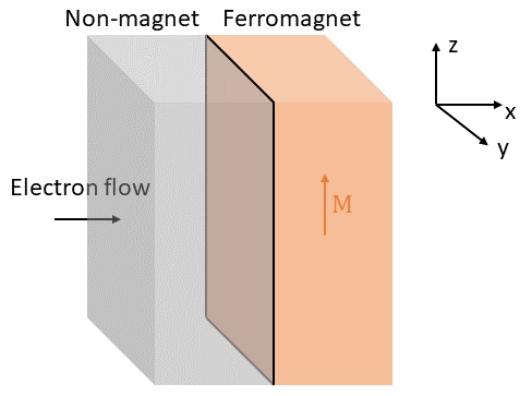
What would happen if you had a F/M/F stack as shown in Figure 5, and you have a reflecting spin current from our original model in Figure 4. What we used to call reflected spin current, is now incoming spin current for the left ferromagnet. When these electrons enter the ferromagnet, they will start to precess around the local field of that ferromagnet, and transfer their transverse momentum to it. So keep in mind that reflecting electrons are responsible for torque on the left ferromagnet as well [10].
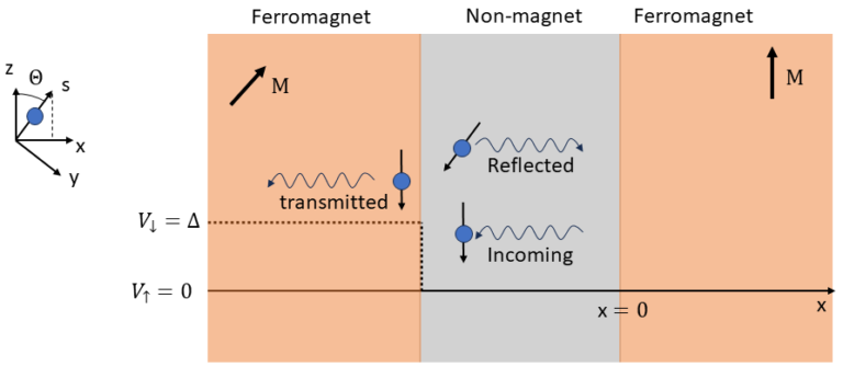
The authors do note that spin currents can flow within a device even if there is no net charge current [6]. This means that STT can also be applied to magnetic materials that do not carry a charge current. One way to look at this, is that the incoming spin-polarized electrons penetrate by diffusive motion into the ferromagnetic material, and transfering their spin angular momentum as discussed before. But for this to happen, an equal amount of electrons leave the material that have (on average) a spin component collinear to the ferromagnet due to conservation of angular momentum.
3. References
[1] L. Berger, Emission of spin waves by a magnetic multilayer traversed by a current, Phys. Rev. B. vol. 54(13), pp. 9353-9358, 1996
[2] J. C. Slonczewski, Current-driven excitation of magnetic multilayers, J. Magn. Magn. Mater, vol. 159, pp. 1-7, 1996
[3] M. Tsoi, A. G. M. Jansen, J. Bass, W. C. Chiang, M. Sec, V. Tsoi and P. Wyder, Excitation of a magnetic multilayer by an electric current, Phys. Rev. Lett. vol. 80(90), pp. 4281-4284, 1998.
[4] J. C. Slonczewski, Currents, torques, and polarization factors in magnetic tunnel junctions, Phys. Rev. B. vol. 71(2), 024411, 2005.
[5] M. D. Stiles, and A. Zangwill, Anatomy of spin-transfer torque, Phys Rev. B. vol. 66, 014407, 2002.
[6] D. C. Ralph, and M. D. Stiles, Spin Transfer Torque, J. Magn. Magn. Mater., vol. 320(7), pp. 1190-1216, 2008.
[7] M. D. Stiles, Spin-Dependent Interface Transmission and Reflection in Magnetic Multilayers, J. Appl. Phys., vol. 79, 5805, 1996.
[8] K. Xia, P. J. Kelly, G. E. W. bauer, A. Brataas, and I. Turek, Spin torques in ferromagnetic/normal-metal structures, Phys. Rev. B, vol. 65, 2020401, 2002.
[9] M. Zwierzycki, Y. Tserkovnyak, P. J. Kelly, A. Brataas, and G. E. W. Bauer, Calculating scattering matrices
by wave function matching, Phys. Rev. B, vol. 71, 054420, 2005
[10] C. Baraduc, and M. Chshiev, Introduction to spin transfer torque, Nanomagnetism and Spintronics, pp. 173-192, 2010.
Florius
Hi, welcome to my website. I am writing about my previous studies, work & research related topics and other interests. I hope you enjoy reading it and that you learned something new.
More Posts