1. Spin-Transfer Torque (STT)
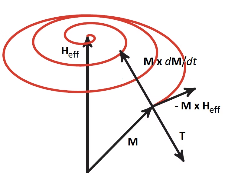
Before we move on to the generation of spin currents by magnetization motion, we first take a look at creating magnetization motion with spin currents. For this, we look at the interface of a normal metal with a ferromagnet, such as cobalt, nickel or iron. Ferromagnets resist changing the strength of their magnetization vector due to high energy costs. Instead, low-energy excitations, known as spin waves (or magnons), affect only the direction of magnetization. The Landau-Lifshitz-Gilbert (LLG) equation describes this magnetization dynamics:
\[\dot{\textbf{m}} = -\gamma\textbf{m}\times\textbf{H}_{eff}+\alpha\textbf{m}\times\dot{\textbf{m}}\]
where,
\[\dot{\mathbf{m}} = \partial \mathbf{m} / \partial t\]
Furthermore, m(r,t) is a unit vector along the magnetization direction, ,γ is the gyromagnetic ratio, and α is the Gilbert damping tensor that determines the rate of magnetization dissipation. The effective magnetic field Heff is derived from the magnetic free energy and saturation magnetization. Additional torques from the interaction between currents and magnetization dynamics need to be added to the LLG equations, with careful consideration of dissipation.
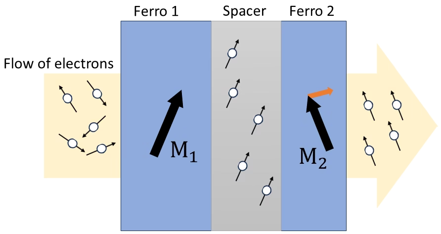
Berger and Slonczewski predicted that in spin-valve structures, where current flows perpendicular to the layers (CPP), a direct current can influence and even reverse the magnetization of magnetic layers separated by a normal metal spacer [1, 2]. This phenomenon has been confirmed by numerous experiments [3, 4].
The interaction between spin-dependent transport and magnetization in ferromagnetic metals involves different electronic structures for majority and minority electron spins. Spins polarized at an angle to the magnetization are seen as a combination of majority and minority spins. When injected at an interface, these states precess and, due to high electron densities in ferromagnets like cobalt, nickel, and iron, interfere destructively, leading to decoherence of the spin momentum. Beyond a transverse magnetic coherence length (about 1 nm), a transversely polarized spin current cannot be sustained [5]. This decoherence generates a torque, known as Slonczewski’s spin-transfer torque, describing the absorption of a spin current at the interface between a normal metal and a ferromagnet.
The transverse components of the spin current are absorbed by the ferromagnet within a nanometer of the interface. This absorption is enhanced by disorder that suppresses residual oscillations. Consequently, spin transfer in transition metal-based multilayers is primarily an interface effect, except in very thin ferromagnetic films [6, 7].
The divergence of the transverse spin current at the interface creates a torque, expressed as:
\[\tau_{stt}^{bias}=-\frac{\gamma\hbar}{eM_sv}\left[G^{(R)}\textbf{m}\times\left(\textbf{m}\times\textbf{V}_N^{(s)}\right)+G^{(I)}\left(\textbf{m}\times\textbf{V}_N^{(s)}\right)\right]\]
where VN(s) is the spin accumulation in normal metal. Adding this torque to the LLG equation results in the Landau-Lifshitz-Gilbert-Slonczewski (LLGS) equation:
\[\dot{\textbf{m}} = -\gamma\textbf{m}\times\textbf{H}_{eff} + \alpha\textbf{m}\times\dot{\textbf{m}} + \tau^{(bias)}_{stt}\]
The first term in the torque equation (Slonczewski torque) resembles Landau-Lifshitz damping. When the spin accumulation VN(s) aligns with the effective magnetic field Heff, this torque enhances the damping and stabilizes the magnetization towards equilibrium. If VN(s) is antiparallel to Heff, the torque opposes the damping, and if it exceeds a critical value, it can cause the magnetization to precess or reverse.
The second term modifies the magnetic field torque and precession frequency. The in-plane torque dissipates the spin accumulation, while the out-of-plane torque induces precession of the spin accumulation in the ferromagnetic exchange field. This spin-transfer torque can be implemented in the Landau-Lifshitz equation, though the conductance parameters will differ.
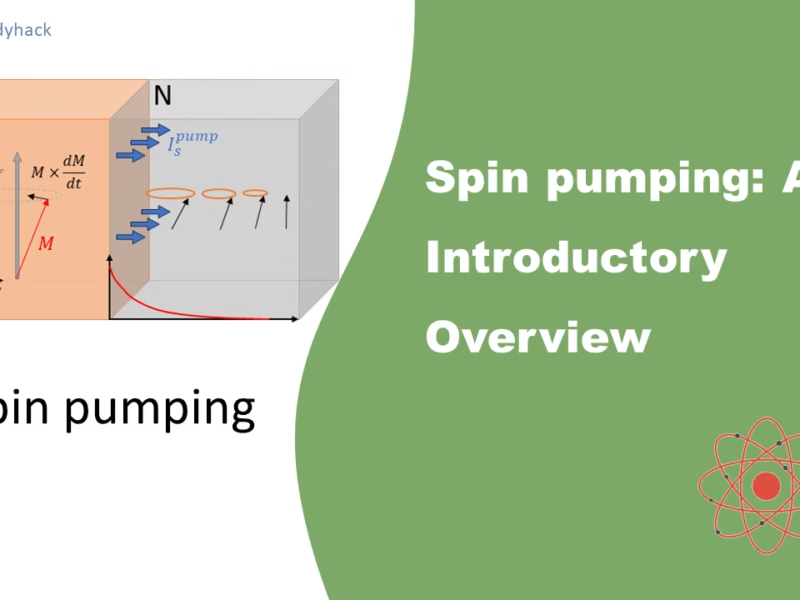
2. Damping mechanism: Spin Pumping
Janossy and Monod [8], along with Silsbee et al. [9], linked dynamic ferromagnetic magnetization with spin accumulation in adjacent metals, explaining enhanced microwave transmission through metals coated with a ferromagnetic layer. Tserkovnyak et al. [10] developed a theory based on adiabatic quantum pumping to explain spin currents induced by dynamic magnetization, calling this process “spin pumping”. Experiments by Mizukami [11]confirmed the theory by showing that spin pumping increases Gilbert damping. In ferromagnet-normal metal systems, dynamic magnetization pumps a spin current polarized perpendicularly to the magnetization vector, with the spin current being proportional to the rate of change of magnetization.
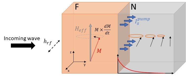
The generation of the spin pumping effect is illustrated in Figure 3. Ferromagnetic resonance (FMR) experiments are normally done to study the damping caused by spin pumping in ferromagnet (F)/normal metal (N) bilayers. In order to test the sample you want to measure when it is placed inside a cavity, and an oscillating rf field (hrf), in the radiofrequency range is applied perpendicular to the external magnetic DC field (HDC). This is done to pull the magnetization (along Heff) out of its equilibrium, and causing it to precess.
The ferromagnet has a large population of its spins in the direction of the magnetization. This shifts the energy band for spin up compared to the spin down by the exchange energy. At the interface, you will have an spin accumulation due to the chemical imbalance. To return to equilibrium state, a spin relaxation process takes place, where a spin tranfers from one band to the other. If this happens in the adjacent layer, it will act as a spin sink. Depending on the properties of this spin sink, it will either relax by spin-flip scattering, or it will flow back into the ferromagnet (this will lead to a current flowing back, Isback. This mechanism happens at not too high temperatures or excitations. Under these conditions the equation for the spin current is [10]:
\[I_s^{(pump)}=\frac{\hbar}{e}\left[g_r^{\uparrow\downarrow}(\textbf{m}\times\dot{\textbf{m}})+g_i^{\uparrow\downarrow}\dot{\textbf{m}}\right]\ ,\]
where gr↑↓ and gi↑↓ are the real and imaginary part of the spin mixing conductance, respectively. In metallic interfaces, the imaginary part is found to be very small and can therefore be neglected as first order approximation. The real part is similar to the damping term found in the LLG equation. The sign of Is(pump) is negative, meaning there is a loss of angular momentum when spin pumping, which leads to an enhanced gilbert damping. Therefore, they normally describe gilbert damping as α = αref + αp, where αref is the normal gilbert damping without a spin sink (metal where the spin current flows to). The damping related to the spin pumping is give by [10]:
\[\alpha^p = \frac{g_r^{\uparrow\downarrow}}{S}\frac{\gamma\hbar}{4\pi M_s}\frac{1}{t_F}\ ,\]
where the damping is proportional to the inverse of the ferromagnet thickness (1/tF).
2.1 What are spin currents?
In electronics, the primary concern is the movement of charge carriers, which are predominantly electrons. In a typical unpolarized current, the electrons have random spins, resulting in an equal number of spin-up and spin-down electrons. Both spin states contribute equally to the charge current.
However, in devices like spin valves, the situation changes. Spin valves are composed of layers of magnetic and non-magnetic materials, which can polarize the spins of the electrons passing through them. This polarization results in an imbalance between spin-up and spin-down electrons, leading to what is known as a spin-polarized current. Here, the electrons’ movement is influenced by both their spin and charge properties.
When we specifically focus on a pure spin current, it refers to the flow of electrons dictated solely by their spin properties, without any net charge movement. In this scenario, electrons with opposite spins move in opposite directions. For example, spin-up electrons may move to the right while spin-down electrons move to the left. This results in no overall charge transfer because the movement of electrons cancels out in terms of charge, but there is a net transfer of spin.
Figure 4 can illustrate this concept: imagine adding two spin-up electrons moving to the right and subtracting two spin-down electrons moving to the left. This creates a net spin current with a spin polarization of +4 to the right, while maintaining zero net charge movement, as the charges cancel each other out. A more rigorous and mathematical explanation can be found in this PhD thesis [13].
![Fig 4. Different currents. (a) Pure charge current, (b) spin-polarized current and (c) pure spin current. In analogy to [12].](https://florisera.com/wp-content/uploads/2024/05/spin-currents-1024x361.png)
2.2 Spin to charge conversion: Inverse spin Hall effect
In conducting materials, the presence of a magnetic field can induce a transverse voltage due to the Lorentz force acting on the moving charge carriers. This phenomenon, known as the Hall effect, results in a voltage that is directly proportional to the magnetic field applied to the conductor [14]. In ferromagnetic materials, there is an additional contribution to the Hall effect known as the anomalous Hall effect (AHE) [15]. This occurs due to the intrinsic properties of the ferromagnetic material itself. The magnetization of the material induces a spin-dependent transverse velocity in the electrons. Because the magnetization defines a preferred direction for the polarization of the charge carriers, the spin-dependent transverse velocity results in a measurable transverse voltage. This voltage is related not only to the external magnetic field but also to the internal magnetization of the ferromagnetic material.
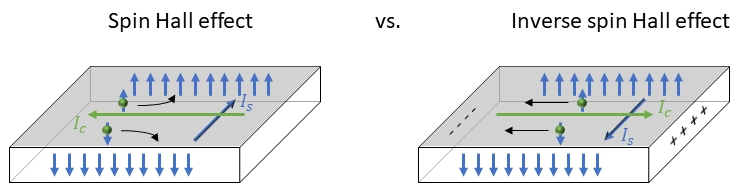
In non-magnetic materials, a similar spin-dependent transverse velocity of electrons occurs due to the spin-orbit interaction. However, in the absence of net magnetization, this does not produce a measurable transverse voltage. Instead, it results in a spin accumulation at the edges of the sample. This phenomenon is known as the spin Hall effect (SHE) [16, 17]. When an electric charge current (IC) flows through the material, it generates a transverse spin current (IS). This means that electrons with opposite spins accumulate at opposite edges of the material, creating a spin current without a net charge movement across the transverse direction.
Conversely, the inverse spin Hall effect (ISHE) describes the process where a spin current can generate a transverse electric charge current [18]. In this case, the flow of spin-polarized electrons (a spin current) induces a measurable electric charge current perpendicular to the direction of the spin current. This mechanic is how we can measure the spin current coming from the ferromagnet into the spin sink (normally a heavy metal layer), by converting it into a charge current that we can see as a voltage.
Charge and spin currents are interconnected through the spin-orbit interaction, which enables the conversion between the two. This coupling and scattering effect allow the transformation of a charge current into a spin current and vice versa. The efficiency of this conversion is characterized by the spin Hall angle (θSHE), which is defined as the ratio of the spin current density to the charge current density (or vice versa).
The ISHE voltage induced by spin pumping can be described as [19]:
\[\begin{equation}V_{ISHE} = \frac{w\theta_{SHE}\lambda_N\textrm{tanh}(d_N/2\lambda_N)}{d_N\sigma_N+d_F\sigma_F}\frac{2e}{\hbar}j_s^0\ ,\end{equation}\]
here, w is the width of the sample (between the two terminals you measure the voltage), dN, σN are the thickness and conductivity of the normal metal, dF, σF are the thickness and conductivity of the ferromagnet, λN is the spin-diffusion length of the normal metal layer, and js0 is the spin current density at the interface. This equation shows that the magnitude of VISHE decreases when the thickness of the metal and/or the ferromagnet layer increases. This is also the reason why you will see thin metal layers (a few nm thick) as spin sink materials.
![Fig 6. (a) The width w dependence of the ISHE signal. (b) The length l dependence of the ISHE signal. (c) The metal layer thickness dependence of the ISHE signal. (d) The ferromagnet layer thickness dependence of the ISHE signal. Taken from [19].](https://florisera.com/wp-content/uploads/2024/05/dependencies.avif)
3. References
[1] L. Berger, Emission of spin waves by a magnetic multilayer traversed by a current, Phys. Rev. B 54, 9353 (1996).
[2] J.C. Slonczewski, Current-driven excitation of magnetic multilayers, J. Magn. Magn. Mater. 159, L1 (1996).
[3] M. Tsoi, A.G.M. Jansen, J. Bass, W.C. Chiang, M. Seck, V. Tsoi, and P. Wyder, Excitation of a magnetic multilayer by an electric current, Phys. Rev. Lett. 81, 493 (1998).
[4] E.B. Myers, D.C. Ralph, J.A. Katine, R.N. Louie, and R.A. Buhrman, Current-induced switching in magnetic multilayer devices, Science, 285, 867 (1999).
[5] A. Brataas, Yu.V. Nazarov, and G.E.W. Bauer, Finite-element theory of transport in ferromagnet-normal metal systems, Phys. Rev. Lett. 84, 2481 (2000); Spin-transport in multi-terminal normal metal-ferromagnet systems with non-collinear magnetizations, Eur. Phys. J. B 22, 99 (2001).
[6] M. Zwierzycki, Y. Tserkovnyak, P.J. Kelly, A. Brataas, and G.E.W. Bauer, First-principles study of magnetization relaxation enhancement and spin transfer in thin magnetic films, Phys. Rev. B 71, 064420 (2005).
[7] A.A. Kovalev, G.E.W. Bauer, and A. Brataas, Perpendicular spin valves with ultrathin ferromagnetic layers: Magnetoelectronic circuit investigation of finite-size effects, Phys. Rev. B 73, 054407 (2006).
[8] A. Janossy and P. Monod, Spin waves for single electrons in paramagnetic
metals, Phys. Rev. Lett. 37, 612 (1976).
[9] R.H. Silsbee, A. Janossy, and P. Monod, Coupling between ferromagnetic and conduction-spin-resonance modes at a aferromagnet-normal-metal
interface, Phys. Rev. B 19, 4382 (1979).
[10] Y. Tserkovnyak, A. Brataas, and G.E.W. Bauer, Enhanced Gilbert damping in thin ferromagnetic films, Phys. Rev. Lett. 88, 117601 (2002).
[11] S. Mizukami, Y. Ando, and T. Miyazaki, The Study on Ferromagnetic Resonance Linewidth for NM/80NiFe/NM (NM=Cu, Ta, Pd and Pt) Films, Jpn. J. Appl. Phys. 40, 580 (2001); S. Mizukami, Y. Ando, and T. Miyazaki, Effect of spin diffusion on Gilbert damping for a very thin permalloy layer in Cu/permalloy/Cu/Pt film, Phys. Rev. B 66, 104413 (2002).
[12] D. Ruffer, Non-local Phenomena in Metallic Nanostructures, Diploma thesis, Technische Universitat Munchen (2009).
[13] F.D. Czeschka, Spin Currents in Metallic Nanostructures, PhD thesis, Technische Universitat Munchen (2011).
[14] E. H. Hall, On a New Action of the Magnet on Electric Currents, Am. J. Math. 2, 287-292 (1879).
[15] E. H. Hall, On the “Rotational Coefficient” in Nickel and Cobalt, Proc. Phys. Soc. London 4, 325 (1880).
[16] M. I. Dyakonov and V. I. Perel, Current-induced spin orientation of electrons in semiconductors, Phys. Lett. A 35A, 459-460 (1971).
[17] . E. Hirsch, Spin Hall Effect, Phys. Rev. Lett. 83, 1834-1837 (1999).
[18] D. Sun et al., Inverse spin Hall effect from pulsed spin current in organic semiconductors with tunable spin–orbit coupling, Nature materials, 15, 863–869 (2016).
[19] K. Ando, et al., Inverse spin-Hall effect induced by spin pumping in metallic system, J. Appll. Phys., 109, 103913 (2011)
Florius
Hi, welcome to my website. I am writing about my previous studies, work & research related topics and other interests. I hope you enjoy reading it and that you learned something new.
More Posts