What are microcontrollers?
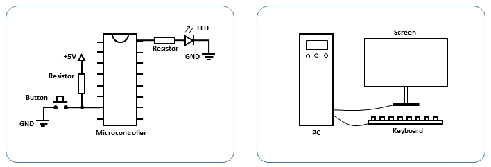
A microcontroller can be considered as a computing system with similar functionality to a personal computer. However, it is important to note that a personal computer is more sophisticated due to its multiple components, such as the CPU, memory, and serial interfaces, which are all integrated into a single chip in a microcontroller. Additionally, personal computers often have peripherals, such as keyboards and screens, to provide input and output functions. Similarly, microcontrollers enable the connection of different components, such as push buttons for input and LEDs to indicate the output, thus enabling analogies to be drawn between the two systems.
Hierarchy of a microcontroller
To comprehend the functioning of a microcontroller, a foundational understanding of basic electrical components is essential. These components include resistors, transistors, and diodes, each serving distinct roles:
- Resistors: They manage the flow of electricity by impeding its progress. This helps in controlling the amount of current flowing through a circuit and also gives a voltage drop across the resistor.
- Transistors: Transistors act like switches, but with an additional control switch. They enable the management of current flow, with the control switch determining when the transistor allows or blocks the passage of current.
- Diodes: Comparable to one-way streets for cars, diodes establish a directional pathway for electricity, allowing current flow in only one direction.
These fundamental components pave the way for constructing logic gates, which are akin to decision-making units in electronics. Consider the AND gate, as shown in the second column in the figure below: just as you might need agreement from both of your friends before making a plan, an AND gate requires both inputs A and B to be active for the output to be active.
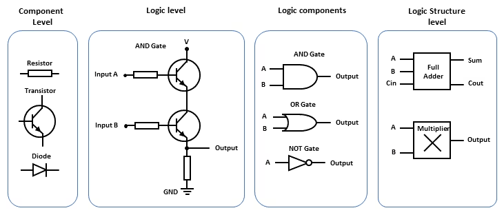
Beyond the AND gate, other logic gates like the OR gate exist. An OR gate produces an active output if at least one of its inputs is active. Similarly, the NOT gate inverts the input signal, essentially switching it from off to on or vice versa.
Combining these logic gates allows for more intricate functionalities, such as arithmetic operations like addition and multiplication. Furthermore, these components can create memory capabilities, similar to your SSD or hard-drive on your computer. The collection of these functions is facilitated by software programs stored within the microcontroller’s memory.
8-bit PIC from Microchip Technology
One of the leading microchip manufacturer is Microchip Technology. They offer a wide range of microcontrollers with varying features, capabilities, and architectures to suit different application requirements. They have microcontroller units (MCUs), digital signal controllers (DSCs) and microprocessors (MPUs). The MCU has different versions, split into 8-bit, 16-bit and 32-bit units. This number refers to the word size or the number of bits that a microcontroller’s or microprocessor’s central processing unit (CPU) can process at a time. This word size affects various aspects of the microcontroller’s capabilities, including memory addressing, arithmetic precision, data processing speed, and overall performance, but also increases in complexity.
PIC16F family
The PIC16F family is a series of 8-bit microcontrollers (MCUs) developed by Microchip Technology. These microcontrollers are widely used in various embedded systems and applications due to their versatility, low power consumption, and ease of use. The PIC16F family is part of Microchip’s PIC (Peripheral Interface Controller) series and has been popular in the electronics industry for many years.
These microcontrollers typically include Flash memory for program storage. PIC16F microcontrollers are known for their low power consumption, making them suitable for battery-powered and energy-efficient applications. They are are often chosen for cost-sensitive applications due to their affordability and wide availability.
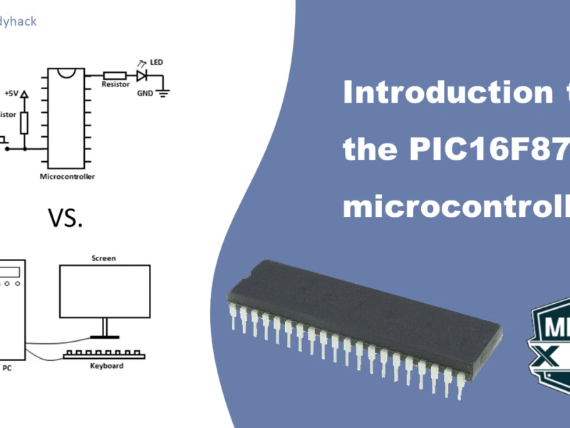
PIC16F877A
the PIC16F877A is known for its ease of use and well-documented resources, which can benefit both beginners and experienced developers. In the next courses we will go over the PIN diagrams and all the functions it can offer. For now, lets focus on how they actually look like.
They come in different package types, and before you randomly start buying the wrong package, you should know what each package is for and if it fits your project. All three packages can be seen in the figure below.
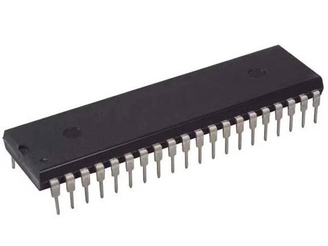
- P DIP (Plastic Dual In-Line Package):
- P DIP is a traditional package type that has been widely used for decades.
- It consists of two parallel rows of pins or leads that extend from the sides of the package.
- The pins are inserted into holes on a printed circuit board (PCB) for soldering, making it suitable for through-hole assembly and allowing you to use traces on both sides/layers
- P DIP packages are commonly used in older electronic systems, hobbyist projects, and applications where easy manual soldering and repair are important.
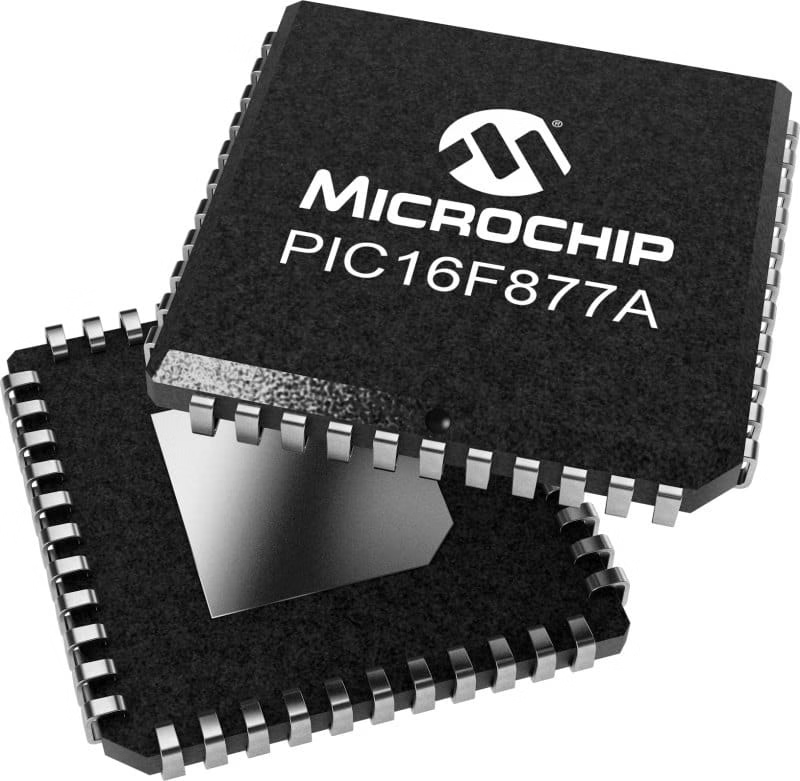
- TQFP (Thin Quad Flat Package):
- TQFP is a surface-mount package type that is more compact and suited for modern electronics.
- It features a square or rectangular body with leads on all four sides in a grid pattern.
- TQFP packages are designed for surface-mount technology (SMT), where the leads are soldered directly to pads on the PCB’s surface. This can be tricky if you’ve never soldered this type of package before.
- They provide higher component density, better thermal characteristics, and are more suitable for automated assembly processes.
- TQFP packages are commonly used in a wide range of applications, including consumer electronics, industrial equipment, and more.
- PLCC (Plastic Leaded Chip Carrier):
- PLCC is another surface-mount package type designed for SMT assembly.
- It features a square or rectangular body with leads that extend outward and then bend down at the corners, allowing for soldering onto the PCB. Again, this can be difficult for the novice.
- PLCC packages typically have pins arranged in a grid pattern around the sides of the package.
- PLCC packages offer good thermal performance and mechanical stability.
- They are often used in applications where space is a concern, such as laptops, networking equipment, and automotive electronics.
In summary, P DIP is a classic through-hole package type, TQFP is a modern surface-mount package with leads on all sides, and PLCC is another surface-mount package with leads that bend down at the corners. Please note that the pin layout is different for each package. In this course we will only discuss the P DIP package. If you plan on using other packages, check the datasheet for the correct pin diagram.
What is next?
In the next section of PIC16F877A programming, we will go over the pin diagram of the PIC16F877A, what pins are important for programming it with the PICKIT3 and discuss the General Purpose Input Output (GPIO) of the microchip.