In this article we take a closer look at the Universal Synchronous Asynchronous Receiver Transmitter, also called USART. This module, also referred to as the Serial Communications Interface (SCI), is a crucial hardware module that enables a microcontroller to communicate with other devices via serial communication. This is the first of three articles explaining serial communications in PIC16F877A. The other two are I2C and SPI. Here we solely focus on the USART module; what it is and how it works. This article gives a short introduction into USART, to give you the basic understanding. The second part discusses the hardware, and the difference between asynchronous (UART) and synchronous (USRT) modes. After that we will delve a bit in possible USART protocol. With all this knowledge we can start explaining on how to configure the devices so they can work in a point-to-point system between two different PIC16F877A devices. The tutorial is written for this particular microcontroller, but can easily be translate to other PIC MCUs.
1. Introduction to USART
As previously mentioned, USART stands for Universal Synchronous Asynchronous Receiver Transmitter. It’s a hardware communication module or peripheral found in many microcontrollers and microprocessors. The acronym itself breaks down the key functions and capabilities of this module:
- Universal: USART is versatile and can handle different types of serial communication, making it suitable for various applications.
- Synchronous: USART can operate in synchronous mode, where data is transmitted with synchronized timing, ensuring that both the sender and receiver are in sync using a shared clock signal. This mode is useful for high-speed and precise communication.
- Asynchronous: USART can also operate in asynchronous mode, where data is transmitted without a shared clock signal. Instead, it relies on the sender and receiver agreeing upon a specific baud rate (communication speed). This mode is more straightforward and is commonly used for lower-speed communication.
- Receiver and Transmitter: USART includes both receiver and transmitter functionality, allowing a microcontroller to both send (transmit) and receive data through serial communication.
In the past USART was used in desktop computers, where it would control the serial port under the name of RS-232. This port was used for modems, mice, keyboards and other peripherals. However, with the invention of much faster USB standards, it is no longer used in recent PCs. However, that does not mean it is of no use anymore. Most Programmable Logic Controllers (PLCs) still use it. Same for the field of robotics or in heating/air ventilation systems. Obviously, it is still used in embedded software, such as in microcontrollers and Internet of Things (IoT).
Due to RS-232 having some disadvantages, such as short distance, low data rate, and more, there was another standard as well. The “updated” version was called RS-485, which adapted newer techniques such as Balanced Differential Signaling, giving this new standard a higher noise immunity then its predecessor. Furthermore, it allowed for higher data rate at much larger distances, and also allowed up to 32 devices to be connected at the same time.
Keep in mind, that using these kind of standards, it will increase the complexity of the (hardware) system. RS-232 requires the use of both positive and negative voltages. The MAX232 IC can be used for interfacing microcontrollers with RS232. It generates the necessary RS232 voltage levels from the microcontroller’s logic levels.
2. Physical Layer
2.1 Asynchronous (UART) Full-Duplex
To send and receive data, we typically use only 2 pins on each device. The pin layout for the PIC16F877A is as follows:
- Serial Port pin Transmission (_TX_) – RC6/TX/CK
- Serial Port pin Receiving (_RX_) – RC7/RX/DT
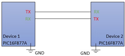
In full-duplex asynchronous USART communication, there are no master-slave roles; both devices are peers that can independently transmit and receive data. Here’s how it typically works:
- Peer-to-Peer Communication: Both devices can act as transmitters and receivers simultaneously, with dedicated TX and RX lines for each.
- Independent Clocking: Each device has its own internal clock source, determining data transmission and reception timing, eliminating the need for clock synchronization.
- No Central Control: Unlike some protocols with master-slave relationships, there’s no central control or arbitration; both devices operate independently and asynchronously.
- Flow Control Consideration: To prevent data overflow or loss, it’s crucial to consider flow control mechanisms, including hardware (RTS and CTS signals) or software-based approaches.
2.2 Synchronous (USRT) Half-Duplex
To send and receive data, we use only 2 pins on each device. The pin layout for the PIC16F877A is as follows:
- Serial Clock pin (_CK_) – RC6/TX/CK
- Serial Data pin (_DT_) – RC7/RX/DT
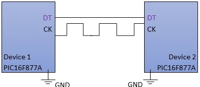
Synchronous half-duplex USART communication involves two devices alternating between transmitting and receiving data over a shared link. Key characteristics include:
- Master-Slave Roles: Master Device: Initiates communication, controls timing, and generates the synchronization clock. Slave Device: Responds to commands, transmits upon instruction, and receives data from the master when addressed.
- Shared Clock Signal (CK): The master generates and shares a clock signal (_CK_) to synchronize both devices.
- Clock Polarity and Phase: Clock polarity (CPOL) and phase (CPHA) settings dictate data bit sampling concerning the clock signal. See the article on SPI for more information on this topic.
- Sequential Operation: Communication unfolds sequentially: the master sends commands or addresses, and addressed slaves respond accordingly.
- Bus Arbitration: The master device governs the communication bus, dictating when devices can transmit and receive. Multiple slaves can share the bus.
- Collision Avoidance: To prevent data collisions, only one device transmits at a time. Devices alternate transmitting and receiving under the master’s control.
USART can be used in either synchronous or asynchronous mode. In this tutorial, we will focus mainly on asynchronous mode.
3. UART Protocol
The UART protocol is organized in data packages, beginning with a Start bit, and ending with a Stop bit. In between, you will find the Data Frame and the optional Parity bit. During the idle state, UART will pull the lines HIGH.
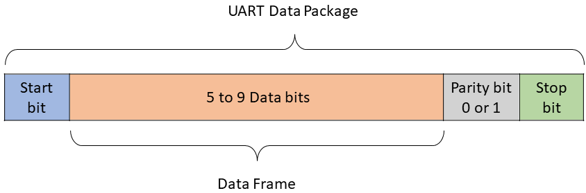
Start bit
Hence for one device to broadcast that he will start sending data, it will pull the line LOW; this is considered the Start bit. The receiving device will notice that the line goes to HIGH to LOW transition, and start listening. It will start reading incoming bits one by one with the frequency that is specified by the Baud Rate.
Data Frame
Directly after, the data bits will be send out. This can range from 5 to 9 bits, depending on your architecture and which MCU you are using. Most often it will be 8, but this is left to the programmer to decide.
Parity bit
A parity bit is a low-level error detection mechanism and it can either be Even (0) or Odd (1). The receiver will check the incoming data and counts the amount of HIGH bits. This number can either be Even or Odd, and it will be checked with the parity bit. In the case the two are the same, it means that the transfer of the byte was a success.
Stop bit
The Stop bit signals the end of the transfer and is shown by a LOW to HIGH transition. It is possible to directly start another transfer right after, but this transfer has to go through the proper Data Package structure, starting with a Start bit.
3.1 Baud Rate
The term “Baud Rate” has been mentioned before when talking about frequency or clock rate. As UART does not have a synchronous clock line, each device has to create its own sampling frequency, which in this case is called the Baud Rate. For initializing full-duplex asynchronous UART, we need to look at the baudrate register (SPBRG) and the transmit/receive status and control registers (TXSTA/RCSTA). We will start by configuring the the baud rate, which determines the communication speed. It is important to note that the baud rate should be the same across all involved devices.
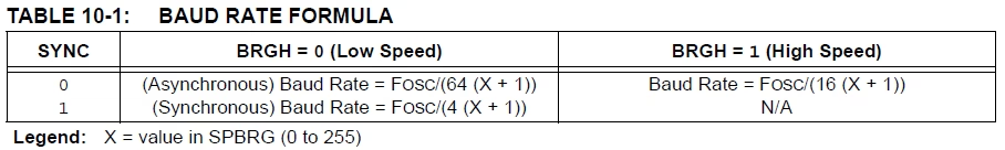
To set the correct Baud Rate, we look at the SYNC and BRGH bits, as shown above. For this example we configure the MCU to high speed baudrate by changing the followig bits:
- TXSTAbits.SYNC = 0; and
- TXSTAbits.BRGH = 1;
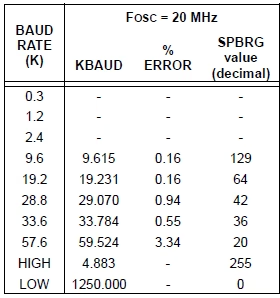
When you choose the correct Baud Rate (low or high speed), you still need to set the value X of the corresponding formula. This is configured in the SPBRG register and has between 0 and 255. The datasheet of your particular PIC microcontroller provides a list of different values, and their corresponding baud rates and error percentage, an example is shown below. In this tutorial we set it to 9.6 kBAUD, which corresponds to SPBRG = 129;
4. Functionality
Asynchronous Full Duplex communication protocol operates in a distinct manner, differing from other protocols due to its bi-directional nature and lack of a Master-Slave structure. The aim of this chapter is to provide an in-depth explanation of its functionality, including efficient transmission and receipt of data. All the functions described here, can be applied to any of the devices, but rather then implement all the functionalities, you should aim for using only what is strictly necessary. The following registers are used for USART:
| Registers | Description |
|---|---|
TXSTA |
Transmit status and control register. |
RCSTA |
Receive status and control register. |
SPBRG |
Baud Rate generator register. |
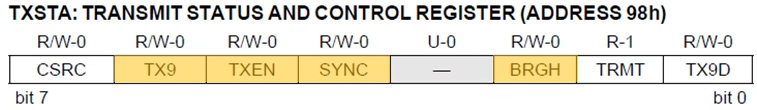
TX9: 9-bit Transmit Enable bit
1 = Selects 9-bit transmission
0 = Selects 9-bit transmission
TXEN: Transmit Enable bit
1 = Transmit enabled
0 = Transmit disabled
SYNC: USART Mode Select bit
1 = Synchronous mode
0 = Asynchronous mode
…
BRGH: High Baud Rate Select bit
Asynchronous mode:
1 = High speed
0 = Low speed
Synchronous mode:
Unused in this mode
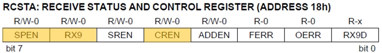
SPEN: Serial Port Enable bit
1 = Serial port enabled (configures RC7/RX/DT and RC6/TX/CK pins as serial port pins)
0 = Serial port disabled
RX9: 9-bit Receive Enable bit
1 = Selects 9-bit reception
0 = Selects 8-bit reception
…
CREN: Continuous Receive Enable bit
Asynchronous mode:
1 = Enables continuous receive
0 = Disables continuous receive
Synchronous mode:
1 = Enables continuous receive until enable bit CREN is cleared (CREN overrides SREN)
0 = Disables continuous receive
4.1 Initialization
The first step is to initialize UART in asynchronous mode with the correct baud rate. This can be done by the following few steps:
- Set the baudrate as shown in chapter 2.
- Configuring TX and RX pins as IO.
- Enabling the serial port (TX and RX).
- Configuring the data frame format: 8-bit data, no parity, 1 stop bit.
- (Optional) Enabling interrupts.
					// Function to initialize UART
void UART_Initialize()
{
    // Configure the serial port control registers

    // 1. Set the Baud Rate
    BRGH = 1;
    SPBRG = 129; // For 9600 baud rate at 20MHz oscillator frequency
                // (Refer to the PIC16F877A datasheet for your value)

    // 2. Configure the TX and RX pins as IO
    TRISC6 = 0; // TX pin as output
    TRISC7 = 1; // RX pin as input

    // 3. Enable the serial port (TX and RX)
    TXEN = 1; // Transmit Enable
    CREN = 1; // Receive Enable

    // 4. Configure data frame format: 8-bit data, no parity, 1 stop bit
    SYNC = 0; // Asynchronous mode
    SPEN = 1; // Serial Port Enable (configures RX/DT and TX/CK pins as serial port pins)
    TX9  = 0; // 8-bit data mode
    RX9  = 0; // 8-bit data mode
}
4.2 Transmitting
The transmit function can be done in multiple ways, here I am showing two methods to write a character (char) to another PIC microcontroller. Do note that they achieve the same purpose, which is to transmit the character over the UART communication channel. However there is a subtle difference between them.
Version 1
					void UART_Write(char data)
{
    // Hold the program until TX buffer is free
    while(!TXIF);
    // Load the transmitter buffer with the data
    TXREG = data;
}
Version 2
					void UART_Write(char data)
{
    // Wait until the transmit shift register is empty
    while(!TRMT);
    // Load the transmitter buffer with the data
    TXREG = data;
}
In version 1, the TXIF bit is set when the transmit buffer is empty. This means that the data that was written to the TXREG register has been sent. For version 2, the TRMT bit is also set when the transmit buffer is empty, but it is also set when the UART is transmitting data.
The difference between them is that the first function is less reliable, because the TXIF bit can be cleared by other events, such as an interrupt. Both work and do the same, just make sure that if you choose version 1, it is not being cleared by other events.
4.3 Receiving
On the receiving side, you will want to enable the use of interrupts, this can be done by setting the following bits:
					    // Enable global and peripheral interrupts
    INTCONbits.GIE = 1;  // Enable global interrupts
    INTCONbits.PEIE = 1; // Enable peripheral interrupts
    PIE1bits.RCIE = 1;   // Enable UART receive interrupt
Receiving a single byte
Receiving data can be done with the “Receive Interrupt Flag” (RCIF) in the PIR1 register. When the data is received, this flag will be set and the received data can be obtained. Check my tutorial on interrupts for a refresher.
Version 1
					char UART_ReceiveChar()
{
    while(!RCIF); // Wait for data to be received
    return RCREG; // Return received data
}
Version 2
					void interrupt ISR() {
    if (RCIF) {
        // Read received data and store it in the global variable
        receivedData = RCREG;
    }
}
There is a big difference between these two versions. Version 1 will wait in an endless loop for the flag to be set before it returns the received data. With this method, you are unable to perform any other action. Version 2 uses an Interrupt Service Routine (ISR), that will automatically become active when the flag is set. Like this, you are able to perform other actions when UART is inactive.
You don’t need to manually clear the RCIF flag in the ISR either; it is automatically cleared when you read data from RCREG. However, it’s essential to clear the global variable (receivedData) to ensure that you don’t mistakenly process the same data multiple times.
Receiving multiple bytes
The above statement does not work when multiple bytes are coming in, one after the other. Obviously this is something that should be known beforehand with flow control consideration.
To handle multiple successive characters received over UART, you typically need to adjust your ISR and buffering strategy. Typically, you will not have enough time to perform actions on the received data before a new byte is received. One common approach is to use a buffer to store received characters. The idea is to use an array with multiple entrees, and fill each slot up with a new incoming byte. Here is an example of a modified ISR and buffer approach:
					#define BUFFER_SIZE 64 // Adjust the buffer size as needed

//Global volatile variables
volatile char receiveBuffer[BUFFER_SIZE];
volatile unsigned char bufferIndex = 0;

void interrupt ISR() {
    if (RCIF) {
        receiveBuffer[bufferIndex] = RCREG; // Read received data and store it in the buffer
        bufferIndex++;
    }
}
// Make sure that in the program where you use the data, to reset bufferIndex to 0.
5. UART Examples
In our example we will communicate between 2 PIC16F877A microcontrollers. Every 1 second, device 1 will send a package of 2 bytes to device 2. This package contains whch LED is activated and if it should go ON or OFF.
This example is not a true full-duplex, as it is only a one-way communication, and I removed the unused functions. In that sense, it has more the structure of a master-slave, but it still configured to be full-duplex if you need it to be. I leave it up to you to use it as you see fit.
Program for Device 1 (like a master):
					#include <pic16f877a.h>
#include <xc.h>

// Define the frequency of the external crystal oscillator
#define _XTAL_FREQ 20000000  // 20MHz external crystal oscillator frequency

// Function to initialize UART
void UART_Initialize()
{
    //Initialization as shown in section 2.
}

// Function to transmit a character via UART
void UART_Write(char data)
{
    // As shown in section 3.1; you can choose between code 1 or 2.
}


// Main function
void main()
{
    char dataReceived;
    UART_Initialize(); // Initialize UART

    while(1)
    {
        // Send the pin address (e.g., RA1 or RB3) and action (High or Low)
        UART_Write('A'); // Sending 'A' for RA1
        UART_Write('H'); // Sending 'H' for High
        __delay_ms(1000); // Delay for 5 seconds

        // Send the pin address (e.g., RA1 or RB3) and action (High or Low)
        UART_Write('B'); // Sending 'B' for RB3
        UART_Write('H'); // Sending 'H' for Low
        __delay_ms(1000); // Delay for 5 seconds
    }
}
Program for Device 2 (like a slave):
					#include <pic16f877a.h>
#include <xc.h>

// Define the frequency of the external crystal oscillator
#define _XTAL_FREQ 20000000  // 20MHz external crystal oscillator frequency
#define BUFFER_SIZE 2 // Adjust the buffer size as needed

volatile char receiveBuffer[BUFFER_SIZE];
volatile unsigned char bufferIndex = 0;

// Function to initialize UART
void UART_Initialize()
{
    //Initialization as shown in section 2.
}

// Function to transmit a character via UART
void UART_Write(char data)
{
    // As shown in section 3.1; you can choose between code 1 or 2.
    // In this example, this function can be removed.
}

void interrupt ISR() {
    if (RCIF) {
        receiveBuffer[bufferIndex] = RCREG; // Read received data and store it in the buffer.
        bufferIndex++; //bufferIndex is reset to 0 in the main loop, after setting the LEDs.
    }
}

// Main function
void main()
{
    UART_Initialize(); // Initialize UART

    // Enable global and peripheral interrupts=
    INTCONbits.PEIE = 1; // Enable peripheral interrupts
    PIE1bits.RCIE = 1;   // Enable UART receive interrupt
    INTCONbits.GIE = 1;  // Enable global interrupts

    TRISA1 = 0; // Clear the TRISA1 bit to configure it as an output
    TRISB3 = 0; // Clear the TRISB3 bit to configure it as an output

    while(1)
    {
        if (bufferIndex >= 2)
        {
            // At least 2 bytes have been received and stored in the buffer
            char pin = receiveBuffer[0]; // Get the pin information (RA1 or RB3)
            char state = receiveBuffer[1]; // Get the state (High or Low)

            // Process the received data based on pin and state
            if (pin == 'A' && state == 'H')
            {
                // Activate RA1 and set it to High
                RA1 = 1;
                RB3 = 0;
            }
            else if (pin == 'B' && state == 'H')
            {
                // Activate RB3 and set it to High
                RB3 = 1;
                RA1 = 0;
            }
            // Clear the buffer and reset the index for new data
            bufferIndex = 0;
        }

        // Other tasks can be performed here
    }
}
5.1. Additional simplified code
No ISR needed
In scenarios where the only function of the receiving PIC microcontroller is to read input, it is possible to simplify the code considerably. Assuming that only one byte is received at a given time and a specific delay exists between each incoming byte, allowing the microcontroller ample time to process the received data, an example of the receiving PIC MCU code is as follows:
					#include <pic16f877a.h>
#include <xc.h>
#define _XTAL_FREQ 20000000  // 20MHz external crystal oscillator frequency

// Function to initialize UART
void UART_Initialize()
{
    //Initialization as shown in section 2.
}

// Function to receive a character via UART
char UART_ReceiveChar()
{
    while(!RCIF); // Wait for data to be received
    return RCREG; // Return received data
}

// Main function
void main()
{
    UART_Initialize(); // Initialize UART
    int receivedData = 0;
    while(1)
    {
        receivedData = UART_ReceiveChar();

        if (receivedData == 0)
        {
        //nothing
        }
        else if (receivedData != 0){
        // do something with dataRead, perhaps use it to drive a motor or an LED
        // then set dataRead back to 0
        receivedData = 0;
        }
    }
}
ISR used
We know we only receive a single byte, with enough delay in between to act (drive a motor, turn on an LED, etc.). We can leave the while(1) loop empty. When the while(1) loop is empty or minimal in structure, it is efficient because it allows the microcontroller to consume minimal power while waiting for events or interrupts. It’s often referred to as “blocking” or “polling” the CPU, where the microcontroller essentially waits for external input without actively executing code in the loop.
					#include <pic16f877a.h>
#include <xc.h>
#define _XTAL_FREQ 20000000  // 20MHz external crystal oscillator frequency

// Declare and initialize receivedData as a global variable
volatile char receivedData = 0;

// Function to initialize UART
void UART_Initialize()
{
    // Initialization as shown in section 2.
}

void interrupt ISR() {
    if (RCIF) {
        receivedData = RCREG; // Read received
        // Do something with the receivedData, like drive a motor or turn on an LED
    }
}

// Main function
void main()
{
    UART_Initialize(); // Initialize UART

    // Enable global and peripheral interrupts
    INTCONbits.PEIE = 1; // Enable peripheral interrupts
    PIE1bits.RCIE = 1;   // Enable UART receive interrupt
    INTCONbits.GIE = 1;  // Enable global interrupts

    while(1)
    {
        // Your main code logic here
    }
}
Florius
Hi, welcome to my website. I am writing about my previous studies, work & research related topics and other interests. I hope you enjoy reading it and that you learned something new.
More Posts