In this tutorial we will see what an LCD-screen is, how it works and how it is used. We will continue by connecting it to the PIC16F877A microcontroller with its GPIOs in 8-bit mode. Later on, we will take a quick look at the 4-bit mode, so both can be implemented. This tutorial is made so it can easily be incorporated in other microcontrollers with very little changes.
1. Introduction to LCD screen (HD44780)
Character LCD screens are widely used for displaying text and simple symbols in microcontroller-based projects. These screens are easy to interface with and can provide valuable visual feedback to your PIC microcontroller projects. They are especially useful when you need to display information in a user-friendly manner. One commonly used type of LCD for this purpose is the Character LCD, often based on the HD44780 controller. This particular microchip acts as a bridge between the actual screen and your microcontroller. All the letters, numbers and some symbols are stored in its data; and can therefore be easily used to write a message on the screen.

I2C LCD screen
A second method is by using a I2C module that comes with the LCD screen. This module normally has a PCF8574 or similar chip build into it and allows communication thruogh the SDA and SCL lines. I’ve used this in one of my other articles when creating a live bus tracker shown on a 4×20 LCD screen. For more information on that particular case, check out my article Live Bus Tracker with ESP32.
2. Connecting the LCD screen with the microcontroller
When working with a microcontroller, it’s important to determine whether you have sufficient pins available. Some microcontrollers have limited pins compared to the PIC16F877A. As such, it’s recommended to consider 2 modes for the HD44780: 4-bit and 8-bit.
- 4-Bit Mode: In 4-bit mode, the data lines DB4 to DB7 of the HD44780 LCD are used to send data in two 4-bit nibbles. This reduces the number of required microcontroller pins, making it suitable for projects with limited I/O pins available. To send a byte of data, you send the higher 4 bits first, followed by the lower 4 bits. More on this in Chapter 4 on this webpage.
- 8-Bit Mode: In 8-bit mode, all 8 data lines (DB0 to DB7) are used for sending data, allowing faster data transfer compared to 4-bit mode. This requires more microcontroller pins but can be more straightforward to implement. This is implemented in this tutorial.
A potentiometer is often used to adjust the contrast of the characters displayed on the LCD. The contrast adjustment allows you to make the characters more or less visible based on the lighting conditions. By changing the resistance of the potentiometer, you control the voltage applied to the V0 pin of the LCD, which affects the contrast.
And finally, many HD44780-compatible LCDs also come with a built-in LED backlight. The LED+ and LED- pins (shown in Fig 2 as A and C) are used to control the backlight. By applying a suitable voltage across these pins, you can turn the backlight on or off. Adding a current-limiting resistor in series with the LED+ pin helps control the brightness of the backlight. Normally, this resistance will be roughly 120 Ohm.

2.1 Port Connection
					#define PORTB Lcd_Port //mapping DB0 to RB0, DB1 to RB1, etc.

#define Lcd_EN RD7
#define Lcd_RW RD6
#define Lcd_RS RD7
2.2 LCD Operations
This section focuses on the method to effectively transmit commands and data with the help of timing diagrams. The purpose of this discussion is to provide a comprehensive overview of the three primary command signals – RS, RW, and EN, which are vital to this process. Understanding the use of these signals is essential to sending commands and data.
- RS (Register Select): The RS pin is used to select whether the data being sent to the LCD is a command or character data. When RS is LOW (0), the data being sent is interpreted as a command. When RS is HIGH (1), the data being sent is interpreted as character data.
- RW (Read/Write): The RW pin is used to control the direction of data flow between the microcontroller and the LCD. hen RW is LOW (0), the data bus is in write mode, allowing data to be sent from the microcontroller to the LCD (write operation). When RW is HIGH (1), the data bus is in read mode, allowing data to be read from the LCD to the microcontroller (read operation).
EN (Enable): The EN (Enable) pin is used to enable the LCD to read the data present on the data bus when transferring data. When you want to send data to the LCD (either a command or character data), you set the EN pin HIGH momentarily and then back to LOW. This high-to-low transition “enables” the LCD to read the data on the data bus.
From the timing diagram we can observe that R/W is set to 0 and RS is set to 1(0 when sending commands). It won’t matter if the data is set on the lines before or after setting these pins, the most important is that they should be prior to getting a High-to-Low pulse on EN. The EN pulse should also have a short duration for it to be properly registered.

The function for transmitting a single byte of data is as follows:
					// Function to send data to the LCD (HD44780)
void LCD_DataWrite(char dat)
{
   Lcd_Port=dat;	  // Set the data on the PORT
   Lcd_RS=1;	      // Select the Register for sending data by pulling RS HIGH
   Lcd_RW=0;          // Select Write by pulling RW LOW
   Lcd_EN=1;	      // Send a High-to-Low Pulse at EN pin
   __delay_us(10);
   Lcd_EN=0;          // set EN pin back to LOW
   __delay_ms(2);     // Add a delay to ensure proper timing, and no need for Buffer check
}
The function for transmitting a command is as follows:
					// Function to send command to the LCD (HD44780)
void LCD_CommandWrite(char cmd)
{
   Lcd_Port=cmd;	  // Set the data on the PORT
   Lcd_RS=0;	      // Select the Register for sending a command by pulling RS LOW
   Lcd_RW=0;          // Select Write by pulling RW LOW
   Lcd_EN=1;	      // Send a High-to-Low Pulse at EN pin
   __delay_us(10);
   Lcd_EN=0;          // set EN pin back to LOW
   __delay_ms(2);     // Add a delay to ensure proper timing, and no need for Buffer check
}
2.3 LCD initialize
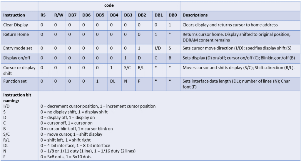
To understand how to initialize the LCD screen, we have to look at the commands we have to send to configure it correctly. These commands can be set to your specific needs, and this table will help you set it up correctly.

In regards to our LCD screen, we want the cursor not to be displayed (C = 0) while also ensuring the text remains within the screen (S = 0). A new character will be automatically moved to the next place (I/D = 1). Please note the instruction set above can help you with your own case. The initialization function for our LCD screen is as follows:
					// Function to initialize the LCD
void LCD_Initialize()
{
    __delay_ms(15);    // 15 ms start up time, as per datasheet
    LCD_CommandWrite(0x38); // "Function set": 8-bit data, 2-line display, 5x8 font. 0b00111000
    LCD_CommandWrite(0x0C); // "Display on/off": Display on, cursor off, blinking off. 0b00001100
    LCD_CommandWrite(0x01); // "Clear Display":  Clear display. 0b00000001
    LCD_CommandWrite(0x06); // "Entry mode set": cursor increments, no display shift. 0b00000110
}
2.4 LCD send Text function
The LCD operation “LCD_DataWrite(char dat)” allows us to transmit single bytes of data to the LCD. To send a string of characters, it is essential to examine the DDRAM address. This address displays the exact location of the text on the LCD. This feature is especially beneficial when the content exceeds the length of a single line, and the text needs to appear on the second line. It is important to note that this does not occur automatically and requires proper programming implementation to operate seamlessly. In this figure we will see the addresses for each digit location. The first slot on the second line has the address 0x40, which in binary is 0b01000000.

According to the datasheet, the command to position the cursor at this specific location is stated as shown in Table 2.

The “LCD_CommandWrite” function automatically manages the RS and R/W signals. It does require the input of the DB7 to DB0 signals. Here the DB7=1 bit is set to locate the right DDRAM address, the DB6-DB0 bits (10000000 in binary or 40 in hex) are the address itself; both combined gives 0b11000000. Thus, to set the cursor to the second line’s first slot, you need to send the value 0b11000000 in binary or 0xC0 in hexadecimal. While you can create a function to set a character to a specific location, this tutorial focuses on transmitting a string of text to the LCD.
The function will verify whether the text exceeds 16 characters in length and subsequently shifts the cursor to the second line.
					void LCD_String(const char* text) {
    int charIndex = 0;

    while (text[charIndex] != '\0') { //continue incrementing untill it reaches the null
        LCD_DataWrite(text[charIndex]);

        // Check if the text is longer than 16 characters & does not have a null on the 17th character
        if (charIndex == 15 && text[16] != '\0') {
            LCD_CommandWrite(0xC0); // Set DDRAM address to second line
        }

        charIndex++;
    }
}
3. Main program - 8-bit mode
To conclude, all functions that are required to interface with the LCD screen are now known, we can write single data bytes, commands, initialize the HD44780 and send texts to be displayed. The main program can be found below.
					#define _XTAL_FREQ 20000000 // Define crystal frequency to 20 MHz
#include <xc.h>
#include <stdint.h> // For uint8_t data type, not used in this example, thus can be removed if needed

// Pin definitions
#define Lcd_EN RD7
#define Lcd_RW RD6
#define Lcd_RS RD5

// Port definitions
#define PORTB Lcd_Port //mapping DB0 to RB0, DB1 to RB1, etc.

// Function to send data byte to the LCD (HD44780)
void LCD_DataWrite(char dat)
{
   Lcd_Port=dat;	  // Set the data on the PORT
   Lcd_RS=1;	      // Select the Register for sending data by pulling RS HIGH
   Lcd_RW=0;          // Select Write by pulling RW LOW
   Lcd_EN=1;	      // Send a High-to-Low Pulse at EN pin
   __delay_us(10);
   Lcd_EN=0;          // set EN pin back to LOW
   __delay_ms(2);     // Add a delay to ensure proper timing, and no need for Buffer check
}

// Function to send command to the LCD (HD44780)
void LCD_CommandWrite(char cmd)
{
   Lcd_Port=cmd;	  // Set the data on the PORT
   Lcd_RS=0;	      // Select the Register for sending a command by pulling RS LOW
   Lcd_RW=0;          // Select Write by pulling RW LOW
   Lcd_EN=1;	      // Send a High-to-Low Pulse at EN pin
   __delay_us(10);
   Lcd_EN=0;          // set EN pin back to LOW
   __delay_ms(2);     // Add a delay to ensure proper timing, and no need for Buffer check
}

// Function to initialize the LCD
void LCD_Initialize()
{
    __delay_ms(15);    // 15 ms start up time, as per datasheet
    LCD_CommandWrite(0x38); // "Function set": 8-bit data, 2-line display, 5x8 font. 0b00111000
    LCD_CommandWrite(0x0C); // "Display on/off": Display on, cursor off, blinking off. 0b00001100
    LCD_CommandWrite(0x01); // "Clear Display":  Clear display. 0b00000001
    LCD_CommandWrite(0x06); // "Entry mode set": cursor increments, no display shift. 0b00000110
}

void LCD_String(const char* text) {
    int charIndex = 0;

    while (text[charIndex] != '\0') { //continue incrementing untill it reaches the null
        LCD_DataWrite(text[charIndex]);

        // Check if the text is longer than 16 characters & does not have a null on the 17th character
        if (charIndex == 15 && text[16] != '\0') {
            LCD_CommandWrite(0xC0); // Set DDRAM address to second line
        }

        charIndex++;
    }
}

void main() {
    // Port B is connected to data lines of the LCD (DB0 to DB7)
    TRISB = 0x00; // Set PORTB as output
    PORTB = 0x00; // Clear PORTB initially

    // Port D pins for control lines
    TRISD = 0x00; // Set PORTD as output, note that RD0 to RD4 are also outputs now
    PORTD = 0x00; // Clear PORTD initially

    // LCD initialization
    LCD_Initialize();

    // Display "Hello World!" on the LCD
    LCD_String("Hello World!");

    while (1) {
        // Your main program logic here
    }
}
4. Example of 4-bit mode
For certain projects, you will not have 8 + 3 pins available for interfacing with the LCD screen. That is why it is also possible to use only 4 data lines + 3 signal lines, reducing the total amount to only 7 pins. This will slightly change how the program works, in particularly the LCD_DataWrite, LCD_CommandWrite and LCD_Initialize functions.
In the LCD_Initialize function, you will have to change the DL bit to 0 inside the “Function Set” to 4-bit mode. The new command inside the LCD_Initialize function will be:
					// Inside the LCD_Initialize() function
LCD_CommandWrite(0x28); // "Function set": 4-bit data, 2-line display, 5x8 font. 0b00101000
The LCD_CommandWrite function will need to be modified to send 2x 4 bits. It is important to note that the DL bit, which sets the mode to 4-bits, is located in the first nibble (4 bits). Once this bit is set, the module will recognize that you are using 4-bit mode and allow you to send the next nibble. Please see the code below for the updated function:
					// Function to send command to the LCD (HD44780) 4-bit
void LCD_CommandWrite(char cmd) {
    // Send the high nibble (4 most significant bits) first
    Lcd_Port = (cmd);          // Set the high nibble on the data lines
    Lcd_RS = 0;                // Select the Register for sending data
    Lcd_RW = 0;                // Select Write mode
    Lcd_EN = 1;                // Pulse the Enable pin
    __delay_us(10);
    Lcd_EN = 0;

    // Send the low nibble (4 least significant bits)
    Lcd_Port = (cmd << 4);     // Set the low nibble on the data lines
    Lcd_RS = 0;                // Select the Register for sending data
    Lcd_RW = 0;                // Select Write mode
    Lcd_EN = 1;                // Pulse the Enable pin
    __delay_us(10);
    Lcd_EN = 0;

    __delay_ms(2);             // Add a delay for proper timing
}
A similar modification should be applied to the LCD_DataWrite function. The modification requires the input char to be adjusted and the pin Lcd_RS to be set to 1. This additional exercise is left to you. Should you require any assistance, please do not hesitate to reach out.
5. Summary
In this tutorial, we’ve delved into the world of LCD screens, exploring the workings of the HD44780 chip that powers them, and how it seamlessly interfaces with the PIC16F877A microcontroller. We’ve taken a comprehensive journey through the essential functions that enable data transmission, command sending, LCD initialization, and text display. Importantly, this approach caters to both 4-bit and 8-bit parallel input configurations, and we’ve provided illustrative examples of each to make it clearer.
Credits to the following websites who's information helped me:
Florius
Hi, welcome to my website. I am writing about my previous studies, work & research related topics and other interests. I hope you enjoy reading it and that you learned something new.
More Posts


