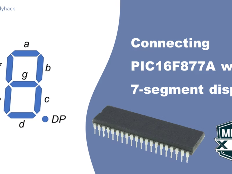
In this tutorial we will see what a 7-Segment display is, how it works and what it is used for. We will continue by connecting it to the PIC16F877A microcontroller, using its GPIO pins.
Introduction to 7-Segment Displays
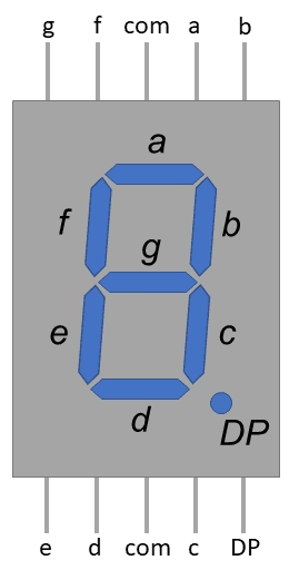
A 7-segment display is a simple electronic component used to visually represent numbers, letters, and some basic symbols. It consists of seven individual LED segments arranged in the shape of the digit “8,” with an additional eighth segment for displaying the decimal point (DP). The segments are labeled from a to g, with each segment representing a specific part of a digit or character.
Each segment can be independently controlled to turn on or off, allowing you to create various combinations to display different numbers and characters. By selectively activating the appropriate segments, you can create the illusion of displaying digits from 0 to 9, some letters of the alphabet, and other symbols.
The 7-segment display is commonly used in a variety of applications where a simple numeric or alphanumeric display is needed, such as digital clocks, calculators, microwave ovens, digital thermometers, electronic scoreboards, and many other electronic devices. It provides a cost-effective and easy-to-use way to present numerical information to users. There are 2 versions of this component:
Common Anode vs. Common Cathode
In a _Common Anode (CA)_ 7-segment display, all the anodes (positive terminals) of the LEDs are connected together and driven by a positive voltage source. Each individual segment’s cathode (negative terminal) is then connected to a specific pin for control. To light up a segment, you apply a low (ground) voltage to its corresponding control pin. This type of display requires sinking current to light up segments.
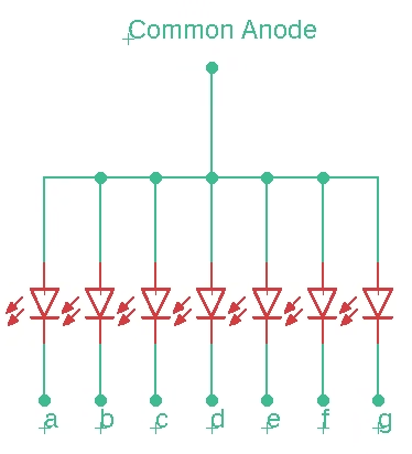
In a _Common Cathode (CC)_ 7-segment display, all the cathodes (negative terminals) of the LEDs are connected together and grounded. Each individual segment’s anode (positive terminal) is connected to a specific pin for control. To light up a segment, you apply a high (positive) voltage to its corresponding control pin. This type of display requires sourcing current to light up segments.
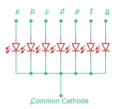
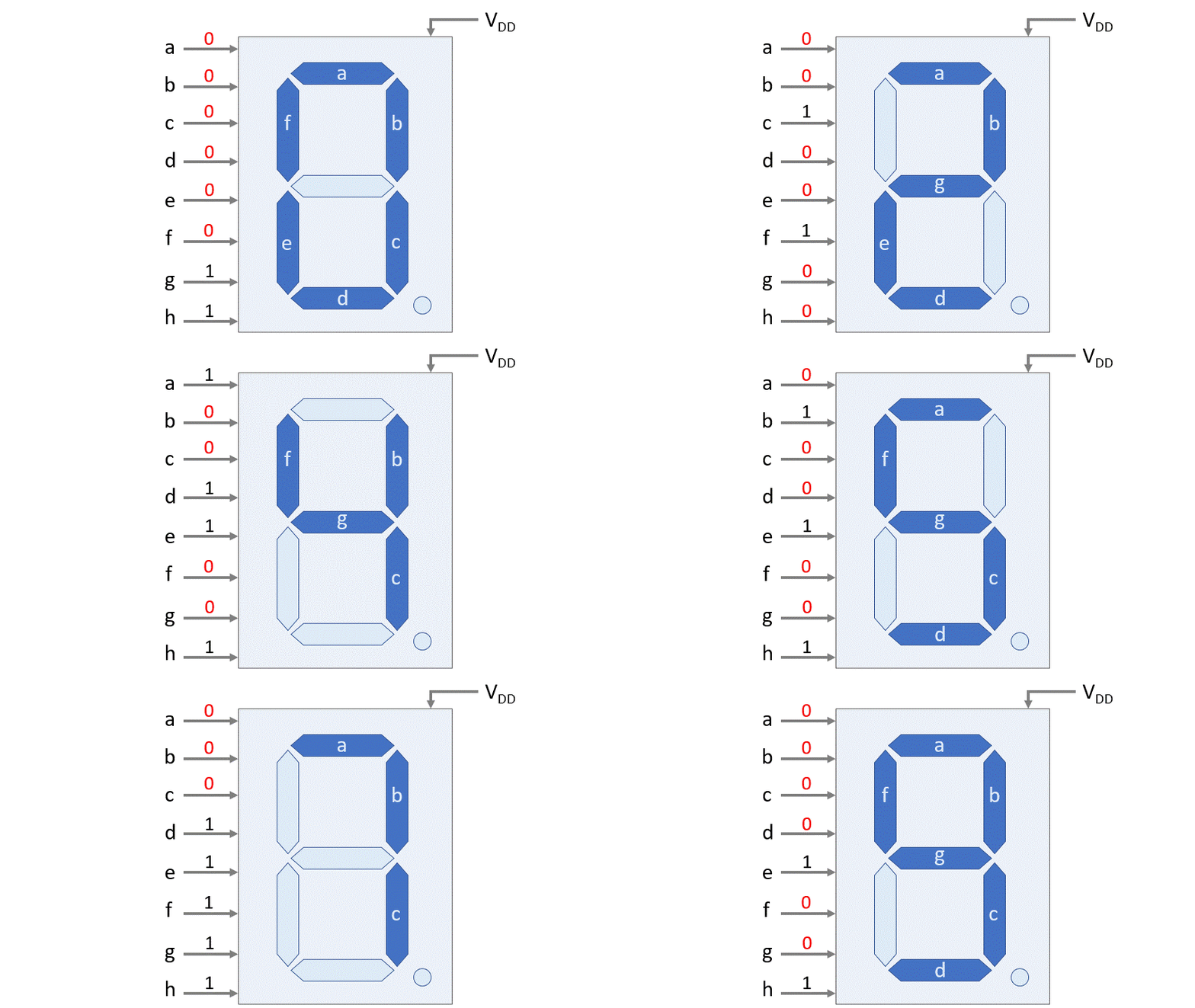
Digital segment for all numbers
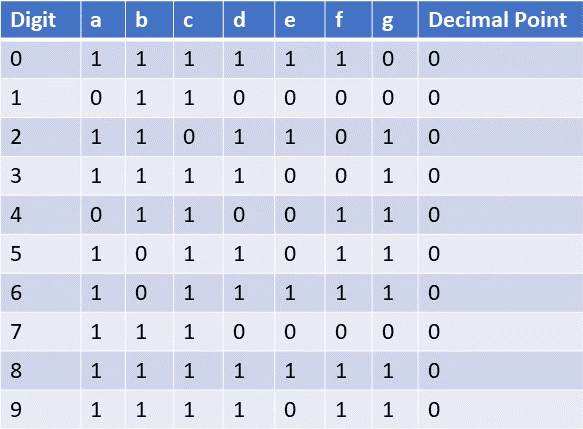
The segments of a 7-segment display are labeled from “a” to “g” and represent different parts of a digit. By selectively lighting up these segments, you can display the numbers 0 through 9. Here’s how each digit is typically displayed using the segments:
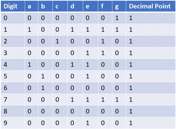
The truth tables for _Common Anode_ and _Common Cathode_ 7-segment displays outline which segments need to be activated to display each digit from 0 to 9. In these tables, each row represents a digit (0 to 9), and the columns represent the segments (a to g). A value of “1” indicates that the segment is pulled high, while “0” indicates that the segment is pulled low. For both cases (_CA_ and _CC_) the decimal point is set off. In most cases it is not even connected in the circuit, and therefore is not lit up.
Interfacing the 7-Segment display with PIC16F877A
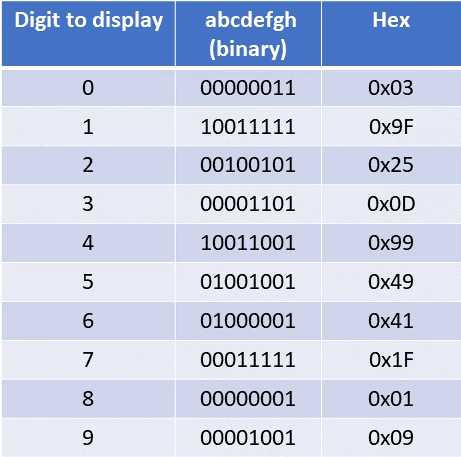
Now we know how 7-Segment displays work, it is time to interface it with the PIC16F877A. The question remains now, how do we connect it; which pin number of the MCU (RD0 to RD7) goes to which pin number of the 7-segment display (a-h). To check that, we have to convert the truth table into binary numbers (and for convenience hexadecimal as well). We will take a look at the _Common Anode_, as this is the most used display, because most PICs are more optimized for sinking current.
From the truth table of the _Common Anode_ 7-segment display, we can use the 7 bits that describe the numbers and the 8th bit for the point and describe them as a binary number as shown here (e.g. for the number 0 we have 0b00000011).
If we’d send all the data directly to PORTD of the microcontroller; we see that the Least Significant Bit (LSB) corresponds to RD0; and that the Most Significant Bit (MSB) corresponds to RD7.

From here we can conclude that RD7 is mapped to ‘a’ on the 7-segment display; RD6 to ‘b’, and so forth.
Circuit diagram
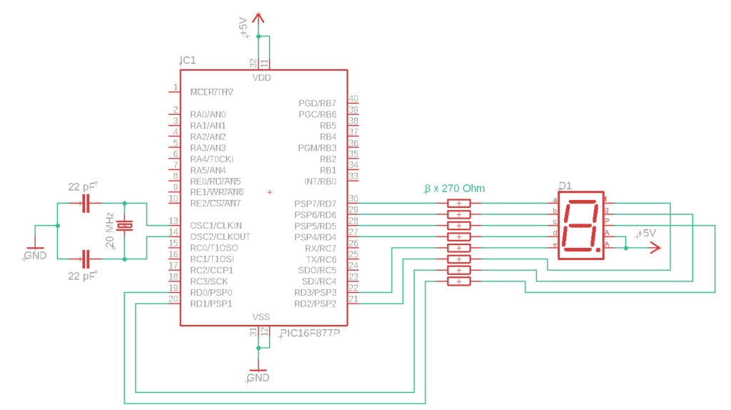
The circuit diagram shows the connections between the PIC16F877A and the _CA_ 7-segment display. As shown in Fig 1, the component has 10 pins, 2 of them are for the common power supply (or ground in case of the CC); and both of them should be connected as shown in this circuit diagram. Furthermore, we should not forget to add the current limiting resistors for each LED in the display. Any resistance around 300 Ohm will suffice.
					#define _XTAL_FREQ 20000000 // Define crystal frequency to 20 MHz
#include <xc.h>
#include<pic16f877a.h>

// Configuration bits settings
#pragma config FOSC = HS        // External Oscillator (HS)
#pragma config WDTE = OFF       // Watchdog Timer Disabled
#pragma config PWRTE = ON       // Power-Up Timer Enabled
#pragma config BOREN = OFF      // Brown-out Reset Disabled
#pragma config LVP = OFF        // Low-Voltage Programming Disabled

void main(void) {
    TRISD = 0x00;  // Set PORTD as output

    // Numbers taken from Fig 6:       0     1     2     3     4     5     6     7     8     9
    unsigned char binary_pattern[] = {0x03, 0x9F, 0x25, 0x0D, 0x99, 0x49, 0x41, 0x1F, 0x01, 0x09};

    while (1) {
    // Cycle through each element of the binary_pattern array and display on the 7-segment display for 1 second each
        for (int i = 0; i < 10; i++) {
            PORTD = binary_pattern[i];
            __delay_ms(1000);  // 1-second delay
        }
    }
}
Summary
Florius
Hi, welcome to my website. I am writing about my previous studies, work & research related topics and other interests. I hope you enjoy reading it and that you learned something new.
More Posts

