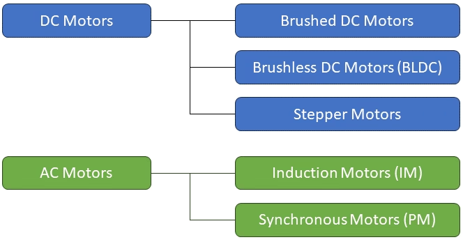
Motors are primarily categorized as either AC or DC, with further classification based on their inherent rotation characteristics. In this article, we will commence by explaining the operation of the brushed DC motor. The subsequent section delves into another type, specifically the brushless DC motor. Finally, we will provide an overview of the main pros and cons of these motors, aiding you in determining the most suitable DC motor for your DIY project.
For those interested, a third type of DC motor exists known as a stepper motor, which is extensively covered in a prior article titled “Controlling Stepper Motors with MCUs.“
Electric motors are the workhorses of countless industries, driving everything from household appliances to complex machinery. At the heart of these motors lies a fundamental choice: Brushed or Brushless DC motors. Understanding the strengths and weaknesses of each type is crucial in optimizing performance for your specific application. Direct Current (DC) motors have been the backbone of electrical machinery for over a century. They operate on the principle of using a magnetic field to generate rotational motion. In a DC motor, current flows in a single direction through a commutator, which, in turn, interacts with the armature to produce mechanical work. This established technology has powered everything from early automobiles to household tools.
Among the pioneers of electrical machinery, Brushed DC motors have stood the test of time. They rely on carbon brushes and a commutator to achieve the crucial task of reversing current direction, enabling continuous rotation. Renowned for their simplicity and robustness, brushed motors find their niche in applications where cost-effectiveness and straightforward control are paramount. In recent decades, technological advancements have ushered in a new era with the advent of Brushless DC motors. These motors eliminate the need for brushes and commutators, instead employing electronic controllers for precise and efficient commutation. This breakthrough innovation has revolutionized industries demanding higher efficiency, lower maintenance, and finer control over motor speed and torque.
The choice between Brushed and Brushless DC motors hinges on a range of factors including application, cost considerations, and desired performance metrics. Each excels in specific scenarios, making informed selection critical for achieving optimal results.
In this comprehensive guide, we will delve into the intricacies of Brushed and Brushless DC motors, exploring their distinct attributes, applications, and the scenarios in which one outshines the other. Join us as we dissect the heart of electric machinery, uncovering the best fit for your unique requirements.
1. Brushed DC Motors
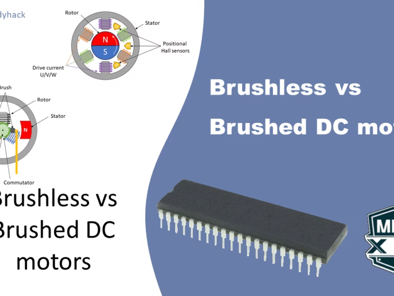
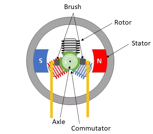
A DC motor operates on the fundamental principle of electromagnetism. It relies on the interaction between a magnetic field and a current-carrying conductor to generate mechanical motion. The motor consists of two main parts, the “rotor” and the “stator“.
- The rotor is the rotating part, located inside of the motor. It contains coils of wire wrapped around an iron core. This assembly is also known as the armature.
- The stator is the stationary part surrounding the rotor. It houses either permanent magnets or field windings, which create a fixed magnetic field.
The rotor’s coils generate their own magnetic field when a current flows through them. This field interacts with the stationary magnetic field produced by the stator. The interaction of these magnetic fields creates a force known as electromagnetic torque.
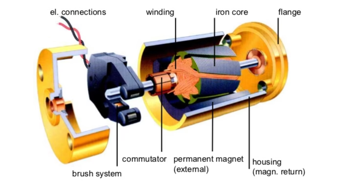
To keep the rotor spinning in one direction, a commutator and brushes are employed. The commutator is a segmented, circular device mounted on the rotor shaft. It acts as a switch to change the direction of current flow in the rotor windings. The brushes are conductive contacts that press against the commutator. They maintain the electrical connection between the rotor and external power source.
As the rotor turns, different segments of its windings are connected and disconnected from the power source by the commutator. This constantly changes the direction of current flow through the rotor coils. This switching of current causes the rotor to be attracted and repelled by the fixed magnetic field of the stator, resulting in continuous rotation.
To energize the armature coils, the brush and the commutator require a good electrical connection. As the commutator rotates, and the brushes are stationary, this will wear down over time until the brushes are worn out completely. That is why many larger brushed DC motors have replaceable brushes. That means they need regular maintenance to replace the brush and eventually the commutator as well.
To control the motor’s speed, torque and direction, we can use an H-bridge. This consists of four electronic switches (usually transistors, IGBTs, or MOSFETs) arranged in a configuration that resembles the letter “H” as shown below. Using a combination of both NPN and PNP transistors, we can create such a configuration, in which the motor’s direction can be reversed. I refer to my previous post on H-bridges for more information. The way to get control over its speed and torque is to also apply a technique called Pulse Width Modulation.
1.1 Types of brushed DC motor
Above we have seen an example of a permanent magnet DC motor, however instead of using permanent magnets, field windings can be used to create a magnetic pole as well. The field windings can be connected in parallel, in series and partly parallel/series to the armature windings. Based on this, these kind of DC motors can be classified as:
- Shunt wound DC motor
- Series wound DC motor
- Compound wound DC motor
1.1.1 Shunt wound DC motors
In case of a shunt wound DC motor, the field windings are connected in parallel to the armature windings. The variation in speed with load is relatively small in a shunt-wound DC motor because the field current, and consequently the field flux and back EMF, remain constant, providing a consistent driving force regardless of the load. This characteristic makes shunt-wound DC motors suitable for applications where a relatively constant speed is required across a range of loads.
However, DC shunt motors are not typically designed for applications with high starting torque requirements. While they can provide moderate starting torque, they are not as well-suited for applications that demand exceptionally high starting torque, such as certain heavy industrial loads or equipment with high inertia as this can damage the motor.
1.1.2 Series wound DC motors
In case of a series wound DC motor, the field windings are connected in series to the armature windings. The field windings carry the whole armature current, and because of this, it can give large torque, which is proportional to the square of the armature current. As the load increases, the armature current increases and the torque increases as well. These series wound DC motors are most suitable for applications which demand large starting torque.
However, as the load decreases (approaching no load), the armature current tends to increase due to the decrease in overall resistance in the circuit. The increase in armature current leads to a higher magnetic field strength, resulting in a higher speed of the motor. This can potentially get out of control and damage the motor.
1.1.3 Compound wound DC motors
A compound-wound DC motor, also known as a compound motor, is a type of DC motor that combines features of both series-wound and shunt-wound motors. In a compound motor, both the series field winding and the shunt field winding are used. This combination allows the motor to exhibit characteristics of both series and shunt motors, offering advantages in terms of torque, speed regulation, and overall performance. For this type, we can classify it further into cumulative and differential compound motors.
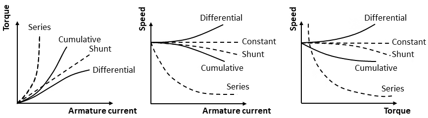
- A cumulative compound motor shares the ability to produce substantial torque at low speeds with a series motor. Nevertheless, it doesn’t exhibit the drawback of the series motor, even under light or no-load conditions. This characteristic allows the cumulative compound motor to operate at a moderate speed without the risk of reaching dangerously high speeds, particularly when the load is minimal or nonexistent.
- In a differential compound motor, the opposing fluxes lead to a reduction in the resultant flux as the load intensifies. Consequently, the motor accelerates at higher speeds under increased loads. This characteristic poses a risk, as under full load, the motor may attempt to operate at dangerously high speeds. Due to this potential hazard, the practical use of differential compound motors is generally avoided.
The exact characteristics of compound wound motors depends on the relative contribution of the series and shunt field windings. In Figure 4, I have tried to give a general view of what to expect from the different motors when different currents/loads are applied.
2. Brushless DC motor
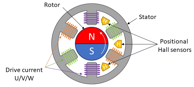
Brushless DC (BLDC) motors, as their name suggests, operate without the use of brushes. You might wonder how current is supplied to the coils without brushes. In brushless DC motors, the coils are not placed on the rotor; instead, the rotor functions as a permanent magnet. The coils are positioned on the stator, as depicted in Figure 5. Since the coils remain stationary on the stator, there is no requirement for brushes and a commutator.
Figure 5 provides an insight into the internal structure of a brushless DC motor. In this particular example, the motor comprises three sets of two coils, each labeled with a distinct color. Each color represents two coils that produce magnetic fields with opposite polarities. To enhance clarity in subsequent examples, we simplify the illustration by using only three stator coils, while maintaining consistent underlying principles. Additionally, the illustration highlights the presence of positional Hall sensors, which provide feedback on the rotor’s position.
Rotation is attained by altering the orientation of the magnetic fields produced by the surrounding stationary coils. Figure 6 illustrates the the steps
2.1 Controlling BLDC motors
Because the coils are on the stator, instead of the rotor, brushes and a commutator are no longer used. This is an advantage, as brushes can wear down over time and have to be replaced. But BLDC motors are more difficult to control, compared to brushed DC motors. With the latter, all you need to do is connect the two brushes to the positive and negative of the power source and it works. BLDC motors have a different number of leads as will be clear below.
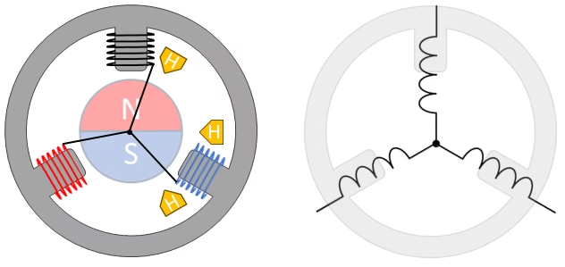
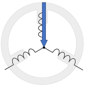
To induce rotation in the rotor, precise management of both the timing and direction of the current flowing through the coils is essential. In our demonstration, a motor with three coils, evenly spaced at 120° intervals, is employed, as depicted in Figure 7. What was previously unclarified is that in BLDC motors, the coils are interconnected in a star pattern, as illustrated on the left side of Figure 7. To further enhance clarity, we replace the coils with their corresponding symbols, as demonstrated on the right side. This visual representation serves as a guide to illustrate the transformative process of electrical energy into mechanical energy within a BLDC motor.
We designate the three coils as U, V, and W. It’s crucial to note that passing electricity through a coil generates a magnetic field, and the polarity of this field depends on the direction of the current. Introducing some terminology, when electric current flows through coil U, we refer to it as phase U, as depicted in Figure 8 (a). The arrow in the figure denotes the generated magnetic flux. Similar designations can be applied for phases V and W.
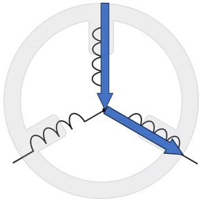
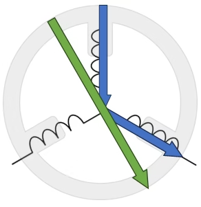
However, it’s important to acknowledge that current cannot flow through a single coil in isolation, as all three coils are interconnected at the center. Figure 8 (b) illustrates the outcome when current flows through coils U and W, forming phase U → W. The figure displays the magnetic fluxes generated by both coils U and W. In Figure 8 (c), the green arrow represents the vector sum of the two blue arrows, also known as the resultant flux. This combined magnetic effect induces the rotation of the permanent magnet, aligning its North (N) and South (S) poles along this resultant flux, with the N pole situated near the arrow’s tip.
To maintain the rotation of the motor, you have to control the current in a specific way so that the rotor keeps chasing the resultant flux. In other words, phase U, V, and W have to be continously switched. Figure 9 shows an animation of the 6 different energization phases and the resultant fluxes. You need to go through modes 1 to 6, to get a full rotation of the motor.
The difficulty in controlling this is due to the fact that the current through the coils has to be reversed. As example, mode 1 where the current flows from U toW, is the reverse of mode 4. In brushed DC motor, this reversal is done through the brushes and commutator. For the BLDC, additional circuitry is required, such as (half) H-bridges.
2.2 Positional feedback
The control of the phases must be in synch with the angular position of the permanent magnet, hence these types of motors normally use a type of sensor to give the positional feedback. As you may have observed, in Figure 5, 6 and 7, we have illustrated small positional Hall sensors. a Hall sensor plays a crucial role in providing feedback on the rotor’s position to the motor controller. The Hall sensor is a solid-state device that detects the presence of a magnetic field.
There are also optical encoders which have higher resolution but give additional overhead and expenses. In addition to these type of sensors, there are ways to use no sensors at all. These “sensorless” BLDC motors rely on other methods, such as back EMF sensing. Back EMF is essentially the voltage induced in the motor’s windings due to the motion of the rotor in the magnetic field. By measuring or sensing this back EMF, the motor controller can infer the rotor’s position and adjust the commutation sequence accordingly.
3. Advantages and Disadvantages
Depending on your application, there are many reasons why you may want to use a BLDC motor over a brushed motor, or vice verse. The following table gives an overview of the main advantages and disadvantages of each motor. It is up to you to decide what is best for your project.
| Brushed DC motor | BLDC motor | |
|---|---|---|
Lifetime |
Short (brushes wear out fast) |
Long |
Speed and acceleration |
Medium |
High |
Efficiency |
Medium |
High |
Noise |
Bad |
Better (or good with sinusoidal control) |
Cost |
Low |
Medium/high |
4. Summary
This article explained the working of a brushed DC motor and a brushless DC motor, and presented a comparison between the two. For more information, I’ve provided some source material down in the links below, that may help you.
Sources
Florius
Hi, welcome to my website. I am writing about my previous studies, work & research related topics and other interests. I hope you enjoy reading it and that you learned something new.
More Posts