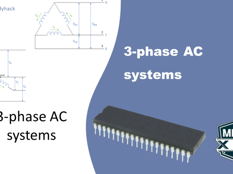
In this article we take a closer look at the three phase power system. I will begin with giving you an overview of the differences between the two types of systems, namely the star connection and the delta connection. The sebsequent two sections will go more in-depth into the equations, and hopefully make it more clear as what those differences entail. If you like to learn more on where this 3-phase power system is used, take a look at my other two articles that deal with AC and DC motors.
1. Three phase power system
A 3-phase power system is a type of electrical power system that uses three separate phases of alternating current (AC) to transmit power. Each phase has a sinusoidal waveform that is offset from the others by 120 degrees. This arrangement of phases allows for a balanced distribution of power and reduces the amount of harmonic distortion in the system.

Three-phase power systems are more efficient than single-phase systems because they can transmit more power over a given conductor size. They are also more reliable, as they are less susceptible to faults. For these reasons, three-phase power systems are the most common type of power system used in industrial and commercial applications.

2. Star connection (Y)
The Star Connection, often denoted as Y, represents a Three Phase Four Wire System (3-Phase 4 Wire), serving as the preferred configuration for AC power distribution. In contrast, Delta connection finds its primary application in transmission scenarios.
Within the Star (Y) configuration, the initiation or termination points (similar ends) of three coils are interconnected, forming the neutral point. This common junction is identified as the Neutral- or Star Point, symbolized by N.
When speaking of a balanced symmetrical load connected across a three-phase voltage system in parallel, three currents flow through the neutral wire. While these currents possess equal magnitudes, they differ by 120° in phase. Mathematically, the vector sum of these three currents is expressed as:
\[I_R+I_Y+I_B=0\]
Examining the electrical potential, the voltage measured between any two terminals or between Line and Neutral (Star Point) is identified as Phase voltage or Star voltage, denoted by VPH. Additionally, the voltage measured between two Lines is known as Line-to-Line Voltage or Line Voltage, denoted by VL.
2.1 Relation between Line voltages and Phase voltages
Figure 1 illustrates both phase voltages (on the left) and line voltages (on the right). The voltages on the three coils are designated with the labels VR, VY, and VB with respect to the neutral point (N). For consistent notation, we refer to the line-to-line voltages as VRY, VYB, and VBR.
To illustrate, consider the calculation of VRY:
\[V_{RY} = V_R – V_Y\]
The above equation can best be seen in Figure 2. Here it is the summation of vector VR and -VY that results in VRY. These designations are used throughout to describe the various voltage relationships in the Y configuration. This ensures a standardized and systematic approach to referencing voltages in the system.
To understand the relationship between line voltages and phase voltage, it is essential to look at the angles between them. The angle between the 3 line voltages is 120°, similar to the 3 phase voltages. However, we are looking at –VY (note the minus sign) and VR and this angle is only 60°. Let’s consider the calculation for VRY:
\[V_{RY} = 2\times V_{PH} \times cos(\frac{60^{\circ}}{2})\]
\[V_{RY} = 2\times V_{PH} \times cos(30^{\circ})\]
\[V_{RY} = 2\times V_{PH} \times \frac{\sqrt{3}}{2}\]
\[V_{RY} = V_{PH} \times \sqrt{3}\]
Similar calculations apply for VYB and VBR. Consequently,
\[V_{RY} = V_{YB} = V_{BR} = V_{L}\ ,\]
\[V_L = V_{PH}\times\sqrt{3}\]
2.2 Relation between Line currents and Phase currents
In Figure 1, each line is intricately connected in series with individual phase windings, illustrating that the magnitude of the line current corresponds precisely to the phase winding to which it is linked.
Let’s denote the currents:
Line 1: IR
Line 2: IY
Line 3: IB
Given that these currents flow through their respective coils:
\[I_R = I_Y = I_B = I_{PH}\]
This establishes a fundamental principle in Y-configurations: the line current (IL) perfectly aligns with the phase current (IPH).
\[I_L = I_{PH}\]
In essence, this signifies that in Y-configurations, the line and phase currents are seamlessly interwoven, a characteristic fundamental to the symmetrical and balanced nature of Y-connected systems.
2.3 Power in Star connection
Active power
Active Power (P) is the actual power which is transfered to the load, such as transformers, motors etc. This power is also called real power, true power or useful power). It is measured in units of Watts (W). It can be calculated by the following calculations:
\[P = V \times I\]
\[P = \sqrt{S^2 – Q^2}\ ,\]
where S is the apparent power, and Q is reactive power.
In three phase AC systems, the total active power is the total sum of all three phase powers. Using the equations we obtained in the previous two sections (IL = IPH and VPH = VL/√3), we can calculate the total active power to be:
\[P = 3 \times V_{PH} \times I_{PH} \times cos \Phi\]
\[P = 3 \times \frac{V_L}{\sqrt{3}} \times I_L \times cos\Phi\]
\[P = \sqrt{3} \times \sqrt{3} \times \frac{V_L}{\sqrt{3}} \times I_L \times cos\Phi\]
\[P = \sqrt{3} \times V_L \times I_L \times cos\Phi\]
We obtain the following two results, where cosΦ is called the power factor.
\[P = 3 \times V_{PH} \times I_{PH} \times cos\Phi\]
\[P = \sqrt{3} \times V_L \times I_L \times cos\Phi\]
The power factor cosΦ is the phase angle between Phase voltages and Phase currents (warning: it is NOT between line voltage and line current!).
Reactive power
Similarly, we can calculate the reactive power (Q). Reactive power is a concept in electrical power systems that represents the power oscillations between the source and the load due to the presence of reactive elements like inductors and capacitors. Unlike real power, which is the actual power consumed by a device and performs useful work (such as lighting a bulb or driving a motor), reactive power does not perform any useful work but is essential for maintaining the voltage levels and stability in a power system.
\[\text{Total reactive power} = Q = \sqrt{3} \times V_L \times I_L \times sin\Phi\]
This total reactive power can be positive for inductive load, and negative for capacitive loads. Its unit is Volt-Ampere Reactive (VAR).
Apparent power
Lastly, we can calculate the apparent power (S). Apparent power is the total power in an electrical circuit, combining both real power (which performs useful work) and reactive power (which does not perform useful work but is necessary for maintaining voltage levels and system stability). Apparent power is measured in volt-amperes (VA).
In an alternating current (AC) circuit, both real power (P) and reactive power (Q) contribute to the apparent power (S). The relationship among these three quantities is described by the following formula:
\[\text{Total apparent power} = S = \sqrt{P^2 + Q^2}\]
Where:
- S is the apparent power in volt-amperes (VA).
- P is the real power in watts (W).
- Q is the reactive power in volt-amperes reactive (VAR).
Apparent power is represented as a complex quantity because it has both a magnitude and a phase angle. The magnitude of the apparent power represents the vector sum of real and reactive power, and the phase angle represents the power factor angle, which is the angle by which the current lags or leads the voltage.
Understanding apparent power is crucial in power systems engineering, as it helps in sizing equipment such as transformers, generators, and power lines to handle both real and reactive power components efficiently. The power factor, defined as the ratio of real power to apparent power, is another key parameter used to assess the efficiency of power systems.
3. Delta connection
The alternative to the Y configuration is the Delta (Δ)-configuration, where the coil terminals are connected as shown in Figure 3. In this configuration, there is no neutral conductor. As such, the voltage between two lines (VL) is equal to the phase voltage VPH of the phase winding, which will become clear in the next sessions.

3.1 Relation between Line voltages and Phase voltages
The line voltage is measured as VRY, VYB or VBR, where the order of the subscript indicates the terminal polarity when each line voltage is positive. The phase voltage VPH is the rms voltage measured across the output terminal of the coils. Just by looking at the configuration in Figure 1, it is quite obvious that the line voltage and phase voltage are the same, hence:
\[V_L = V_{PH}\]
3.2 Relation between Line currents and Phase currents

In a Delta (Δ) configuration of a 3-phase power system, the relationship between the line currents (IL) and phase currents (IPH) can be expressed as follows:
- I1 = IR – IB
- I2 = IY – IR
- I3 = IB – IY
Where:
- I1, I2, and I3 are the line currents for Lines 1, 2, and 3, respectively.
- IR, IY, and IB represent the phase currents for phase R, Y, and B, respectively.
Considering the equality of phase currents in balanced systems (IR = IY = IB = IPH), which happens under a balanced load condition, the line currents can be determined as follows:
\[I_1 = I_L = 2 \times I_{PH} \times cos(\frac{60^{\circ}}{2})\]
\[I_L=2\times I_{PH} \times cos 30^\circ \]
\[I_L =2\times I_{PH} \times \frac{\sqrt{3}}{2}\]
\[I_L= \sqrt{3}\times I_{PH}\]
similarly for \[I_1 = I_2 = I_3 = I_L\]
The vector nature of these currents is evident in the application of vector differences, showcasing the relationship between line and phase currents in a Delta configuration.
3.3 Power in Delta configuration
We know that the total power of the three phases is:
\[P = 3\times V_{PH} \times I_{PH} \times cos\Phi\]
From the previous sections, we know that the values for VPH = VL, and that IPH = IL/√3, thus putting them into the power equation gives the following:
\[P= 3\times V_L \times \frac{I_L}{\sqrt{3}}\times cos\Phi\]
\[P= \sqrt{3}\times\sqrt{3}\times V_L\times \frac{I_L}{\sqrt{3}}\times cos\Phi\]
\[P= \sqrt{3} \times V_L\times I_L \times cos\Phi\ \ \text{or}\ \ P = 3\times V_{PH} \times I_{PH} \times cos\Phi\ ,\]
where cosΦ is the power factor. This is the phase angle between VPH and IPH (not between the line voltage and line current!!).
Florius
Hi, welcome to my website. I am writing about my previous studies, work & research related topics and other interests. I hope you enjoy reading it and that you learned something new.
More Posts


