 Daily tech news
- A tiny light trap could unlock million qubit quantum computersA new light-based breakthrough could help quantum computers finally scale up. Stanford researchers created miniature optical cavities that efficiently collect light from individual atoms, allowing many qubits to be read at once. The team has already demonstrated working arrays with dozens and even hundreds of cavities. The approach could eventually support massive quantum networks with […]
- A strange in-between state of matter is finally observedWhen materials become just one atom thick, melting no longer follows the familiar rules. Instead of jumping straight from solid to liquid, an unusual in-between state emerges, where atomic positions loosen like a liquid but still keep some solid-like order. Scientists at the University of Vienna have now captured this elusive “hexatic” phase in real […]
- New catalyst makes plastic upcycling 10x more efficient than platinumScientists are finding new ways to replace expensive, scarce platinum catalysts with something far more abundant: tungsten carbide. By carefully controlling how tungsten carbide’s atoms are arranged at extremely high temperatures, researchers discovered a specific form that can rival platinum in key chemical reactions, including turning carbon dioxide into useful fuels and chemicals. Even more […]
- Engineers just created a “phonon laser” that could shrink your next smartphoneEngineers have created a device that generates incredibly tiny, earthquake-like vibrations on a microchip—and it could transform future electronics. Using a new kind of “phonon laser,” the team can produce ultra-fast surface waves that already play a hidden role in smartphones, GPS systems, and wireless tech. Unlike today’s bulky setups, this single-chip device could deliver […]
- An old jeweler’s trick could change nuclear timekeepingA team of physicists has discovered a surprisingly simple way to build nuclear clocks using tiny amounts of rare thorium. By electroplating thorium onto steel, they achieved the same results as years of work with delicate crystals — but far more efficiently. These clocks could be vastly more precise than current atomic clocks and work […]
- Critical minerals are hiding in plain sight in U.S. MinesResearchers found that U.S. metal mines already contain large amounts of critical minerals that are mostly going unused. Recovering even a small fraction of these byproducts could sharply reduce dependence on imports for materials essential to clean energy and advanced technology. In many cases, the value of these recovered minerals could exceed the value of […]
Category
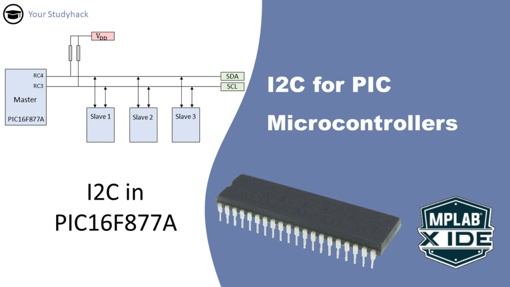
I2C for PIC Microcontrollers
In this article, we will take a closer look at the I2C serial communication protocol. This is the second in a series of three articles...
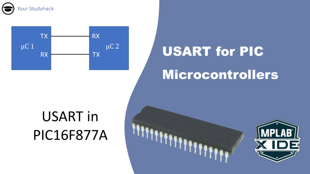
USART for PIC Microcontrollers
The USART module, also referred to as the Serial Communications Interface (SCI), is a crucial hardware module that enables a microcontroller to communicate with other...
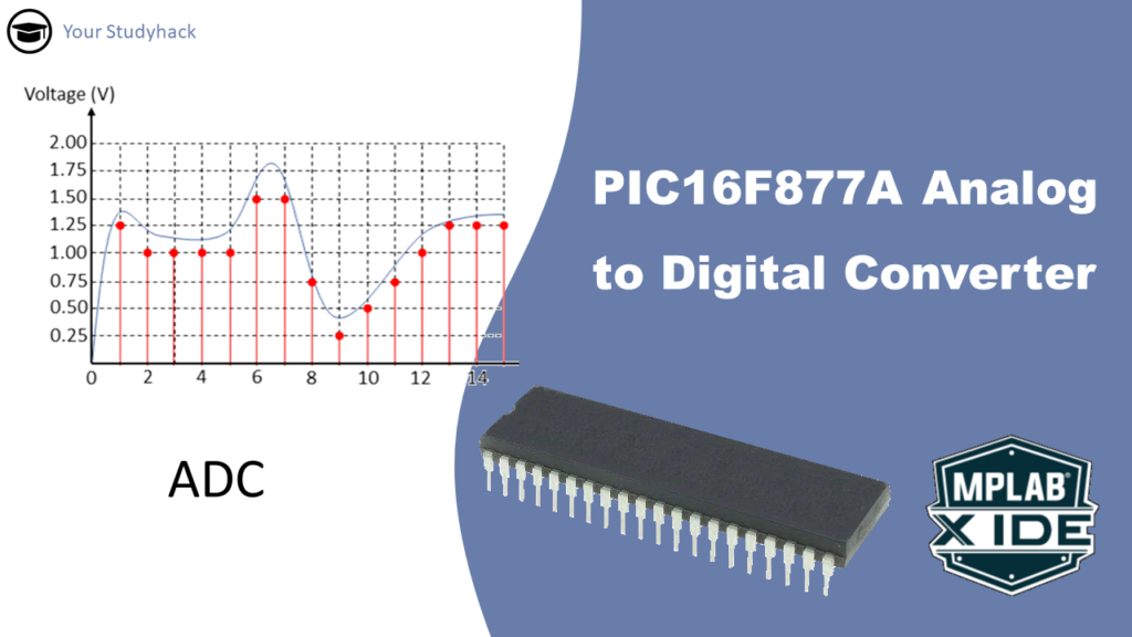
PIC16F877A Analog to Digital Converter (ADC)
The ADC module in microcontrollers indeed allows them to interface with the analog world by converting continuous analog signals into discrete digital values. This capability...
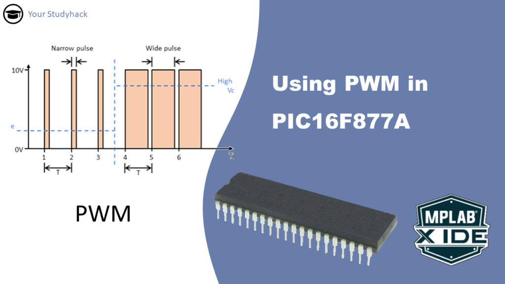
Using PWM in PIC16F877A
Digital signals (0 or 1) and analog signals (range of values) are both used in electronics. Analog inputs can be converted to digital through an...
PIC16F877A Timer2 tutorial
The Timer2 module is an 8-bit timer/counter within most PIC MCU devices. Timer2 can increment up to a value of 255 before it overflows back...
PIC16F877A Timer1 Tutorial
The Timer1 module is a 16-bit timer/counter within most PIC MCU devices. Timer1 can increment up to a value of 65535 before it overflows back...
Prerequisits
To make it easier, I assume you have a basic knowledge of the following:
- Basic circuitry knowledge; such as resistors, transistors, diodes, relays.
- Basic programming knowledge in C; understand what are functions, operators, data types, and more.
- Digital electronics, such as logic gates.
On some occasions I will explain it from scratch, but to understand everything, it is best to brush up on the basics so that you can follow the tutorials.
Required Software
For these tutorials we use Microchip’s own software package that includes:
- MPLAB X IDE
- XC8 Compiler
- PICKIT3 programmer/debugger
All the tools can be downloaded at the official website of Microchip Technology
Required Hardware
The full tutorial consists of many different types of electrical components, sensors and actuators. It depends completely on your own project what you need. However, in all cases you will need a Pickit3 tool to install the software and you need at least 1 PIC16F877A microcontroller to install it on.


