1. Configuring the GPIO with TRISx
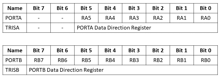
We need to set certain pins to work as General Purpose Input and Output. To do this, we need to look at the 8-bit TRIS register in the PIC16F877A datasheet. An example of port A and B can be seen in the figure below. This data has been taken out directly from the datasheet and it shows the 2 important registers, namely the PORTx and TRISx registers, where x stands for port A, B, C, D or E.

To set a specific pin, or the whole port, as an IO, we need to look at the TRISx register. From the pin diagram, explained in the previous tutorial, we know that port A only has 6 pins and port B has all 8.
- Setting a TRISx bit (=1) will make the corresponding PORTx pin an input.
- Clearing a TRISx bit (=0) will make the responding PORTx pin an output.
For the forgetful: 1 is similar to I of Input, while 0 is similar to O of Output.
1.1 Setting the IO
For setting the pin 0 on port A as output or input, we write the following code:
					TRISA0 = 0; //sets pin RA0 as output
TRISA0 = 1; // sets pin RA0 as input
Similar to setting a single pin, we can set a whole port as input/output by directly writing an 8-bit binary value:
					TRISB = 0b00000000; // sets all pins on port B as output
TRISB = 0b00001111; // Sets pins RA7 to RA4 as output and pins RA3 to RA0 as inputs
In the case of TRISA, bits 7 and 6 are unimplemented and these cells are not used. Thus, in the case of TRISA you could write the following code and it has the same outcome (take caution with TRISE, I recommend to check the datasheet for this).
					TRISA = 0b11000000; //Sets RA5 to RA0 as output
TRISA = 0b00000000; //Sets RA5 to RA0 as output
Binary can also be written in hexadecimal numbers 0 – F. There is no difference in MPLAB, and it depends on your own preference what you would like.
					TRISB = 0b01111001; // In binary
TRISB = 0x79; // In hexadecidemal gives the same result
2. Configuring the GPIO with PORTx
Similar to the TRISx registers, each port has its own PORTx register, as shown in the example figure above, which can be used to read the register or write a high / low to the pin.
2.1 Writing a High or Low on the output
When the pin is set as output with the TRISx register, we can use the PORTx register to set the pin either as low (0V) or high (5V). This can be done by the following:
					RB1 = 0; // Set the output of the pin to low (0V)
RB1 = 1; // Set the output of the pin to high (5V)

PORTB = 0b00000001; // Set all pins of port B to low, besides RB0 which is high
PORTB  = 0xFF; // Set all pins of port B as high
2.2 Reading the input
When the pin is set as a digital input, the value of 0 or 1 is stored in the PORTx register, and we can obtain it by accessing either a single pin (e.g. RB0) or the entire port (e.g. PORTC). In the examples below, I write an example code of how it could look like.
Reading a single pin
					void main() {

    TRISB0 = 1;  // Set RB0 as input

    unsigned char X;

    X = RB0;  // Read RB0 and assign it to X

    // Now X contains the value of RB0 (0 or 1)
    // ... Rest of your code ...
}
Reading the whole port
					void main() {

    TRISC = 0xFF;  // Set all bits of TRISC to 1 to configure PORTC as inputs

    unsigned char inputValues;

    inputValues = PORTC;

    // Now the variable inputValues holds the states of all input pins of PORTC
    // ... Rest of your code ...
}
3. Example with switch & LED
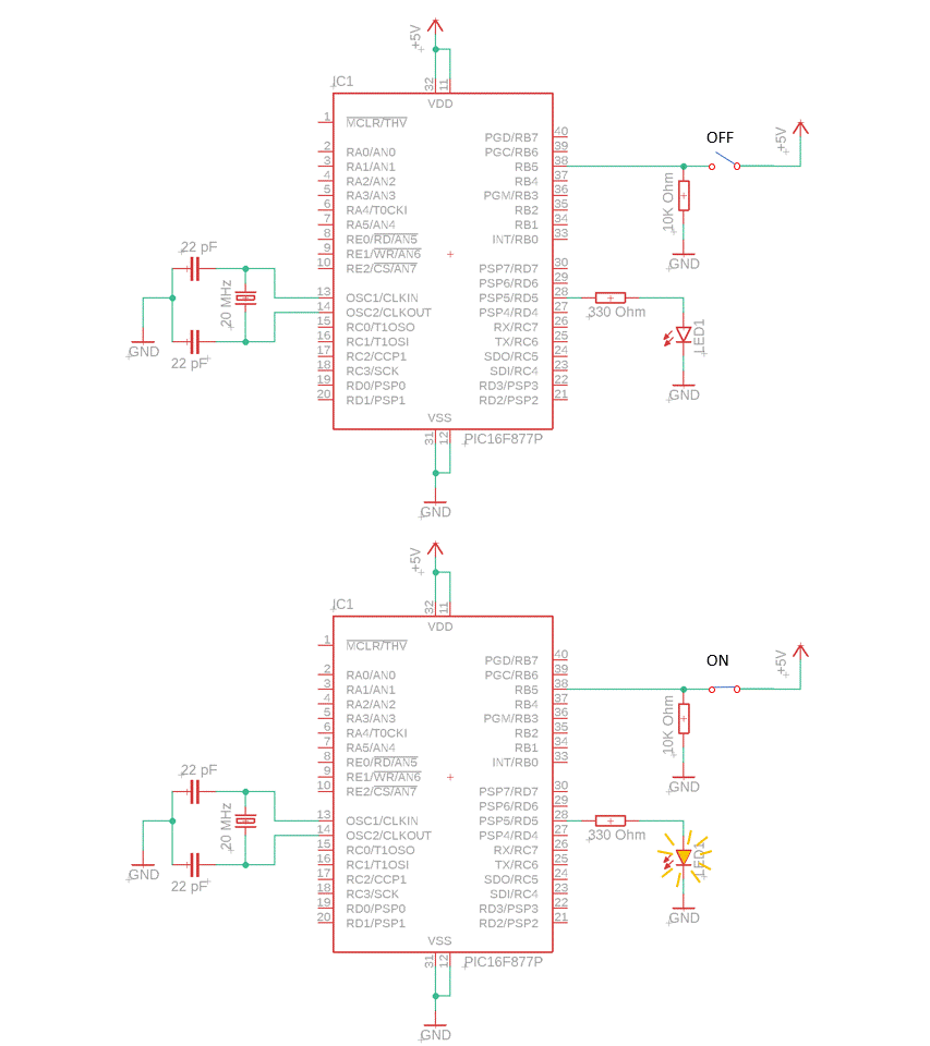
In this demonstration, we will integrate the PIC16F877A microcontroller with a switch, which triggers the activation of an LED upon connection. The switch is connected on one end to the 5V power supply, while on the other side it connects to pin RB5 of the microcontroller. An additional resistor of 10K Ohm is placed that is connected to the ground. The purpose of this pull-down resistor is to ensure that when the button is not pressed, the RB5 pin is pulled to a known logic level (GND). This prevents the input from floating and causing erratic behavior.
On pin RD5 we connect the LED, that is programmed to turn on when the switch is ON, as shown in the Figure below. Why we use a resistor of 330 Ohm in series with the LED is explained in the next tutorial.

The program for the setup above will be the following:
					#include <xc.h>

// Configuration bits
#pragma config FOSC = HS   // External high-speed crystal oscillator
#pragma config WDTE = OFF  // Watchdog timer disabled
#pragma config PWRTE = OFF // Power-up timer disabled
#pragma config BOREN = OFF // Brown-out reset disabled
#pragma config LVP = OFF   // Low voltage programming mode disabled

#define _XTAL_FREQ 20000000 // 20MHz external crystal frequency

void main(void) {
    //Set the pins as GPIO
    TRISB5 = 1; // Set RB5 as input
    TRISD5 = 0; // Set RD5 as output

    RD5 = 0; // Turn OFF the LED initially

    while (1) {
        if (RB5 == 1) {
            RD5 = 1; // Turn ON the LED when switch is ON (RB5 ==1)
        } else {
            RD5 = 0; // Turn OFF the LED when switch is OFF (RB5 == 0)
        }
    }
}
4. Summary
In summary, we learned how to set the general purpose input output using the TRISx register. Furthermore, for outputs we can use the PORTx register to set the output to either Low (0V) or High (5V). For the inputs, we can directly read them and put them in a variable. Finally, we showed an example of a circuit and program for the PIC16F877A microcontroller interfaced with a switch that controls the LED.
