


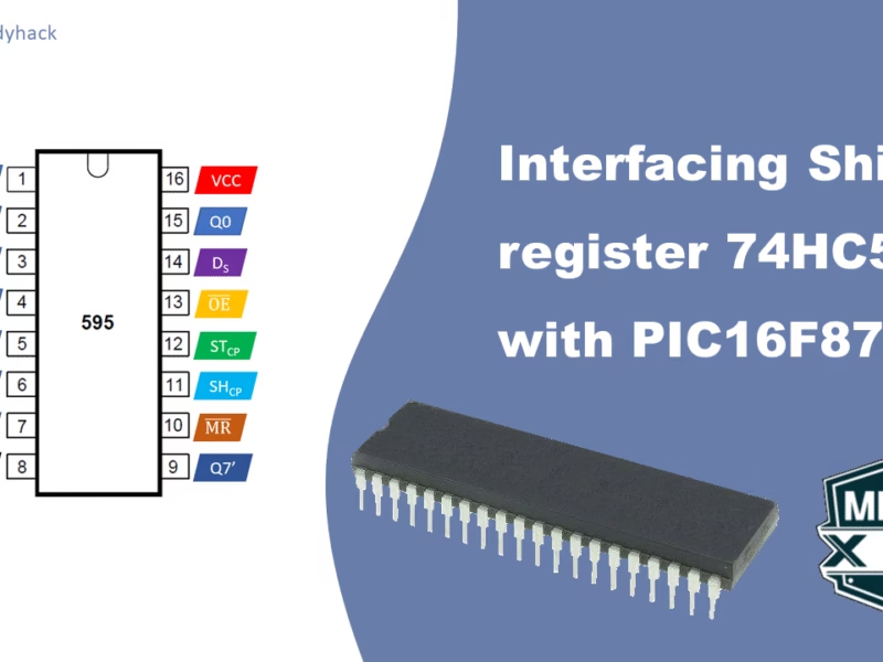
In this tutorial we will learn how to use external interrupts in PIC microcontrollers. We will go in depth on how to set it up in hardware, and how to configure it correctly within the program. For the examples we will use microcontrollers from the PIC16F family; in particular the PIC16F877A.
1. What are interrupts and when do you use them?
An external interrupt is an event that can cause the microcontroller to stop what it is doing and execute a special routine called an interrupt service routine (ISR). The interrupt is typically caused by a change in the state of an external device, such as a button press or a sensor reading. This allows for real-time responses, as the microcontroller can react to the event immediately.
When an interrupt occurs, the ISR is called, and any code that is inside the ISR will be run. Once the ISR is finished, the microcontroller will return to the main program, at the point where it left off. There are several types of interrupts in the PIC16F877A, such as:
- External interrupts,
- Timer 0 (and timer 1) overflow interrupt,
- RB port change interrupt,
- Serial port transmit/receive interrupts,
- ADC/comparator interrupts,
- Watchdog timer interrupt.
To make sure that interrupts dont happen in the wrong order, there is a priority listed to them; the external interrupt has the highest priority of them all, and that is the one we will focus on in this tutorial.
2. Configuring the interrupt settings
Most of the interrupts are configured in the INTCON register, which contains variable flag bits for the TMR0 register overflow, RB port change and external RB0/INT pin interrupts.
The following bits in the INTCON register are relevant to external interrupts:
- GIE: Global Interrupt Enable bit. This bit enables or disables all interrupts.
- PEIE: Peripheral Interrupt Enable bit. This bit enables or disables the peripheral interrupts (Timer 0, Timer 1, Serial Port, A/D Converter, and Comparator).
- INTE: RB0/INT External Interrupt Enable bit. This bit enables or disables the external interrupt.
To set the interrupt settings, you write to the INTCON register. The following table shows the values you need to write to the INTCON register to enable or disable the different interrupts:
| Bit | Value | Description |
|---|---|---|
| GIE | 1 | Enables all interrupts. |
| PEIE | 1 | Enables the peripheral interrupts. |
| INTE | 1 | Enables the external interrupt. |
Once RB0 pin is declared an external interrupt pin, the external interrupt flag, INTF, changes to 1 anytime it becomes low. Consequently, the code inside the void interrupt function will execute since the Interrupt Service Routine (ISR) will be called. Proper knowledge of these concepts is essential for external interrupts function.
2.1 Interrupt Service Routine (ISR)
An ISR, or Interrupt Service Routine, is a special routine that is called when an interrupt occurs. The ISR typically performs the desired action, such as turning on an LED or reading a sensor value.
The ISR is located in the program memory. The following is an example of an ISR for the external interrupt:
					void interrupt ISR() {
        // Perform the desired action.
        INTCONbits.INTF = 0; // Clear the interrupt flag
    }
The ISR is called when the interrupt occurs. The microcontroller will automatically save the state of the registers before executing the ISR. Once the ISR is finished, the microcontroller will restore the state of the registers and return to the main program. It is of vital importance, that you clear the interrupt flag after doing the task, because if another interrupt appears, it will not interrupt the current interrupt, else it might go wrong.
Here are some of the things to keep in mind when writing an ISR:
- The ISR should be as short as possible.
- The ISR should not make any changes to the global variables.
- The ISR should not call any functions that make changes to the global variables.
- The ISR should not call any functions that can cause an interrupt.
2.2 Program code
For this example we will create a program that shows a counter that increments every time the main program is being interrupted by the external interrupt. In this particular example, it is not too different from having a button to increase the counter, however, you must understand that there is a fundamental difference between the two. With the external interrupt, it literally interrupts the program to do the ISR. We will reuse the program code, from one of our previous tutorials on interfacing with an LCD, to display the data.
An important notice; in the original code for LCDs, we used PORTB as 8-bit databus to interface with the LCD. However, we moved all this to PORTC, as RB0 is now the interrupt. In my program code, this was done by just writing “#define Lcd_Port PORTC”. Of course, it can also be changed to 4-bit mode, and only use RB4-RB7 as databus. If you are using any other microcontroller, please consult my page on interfacing with the LCD to learn in just a few steps how to set it up for your particular case.
					#include <xc.h>
#include <stdint.h>

#define _XTAL_FREQ 20000000

// Configuration bits settings
#pragma config FOSC = HS        // External Oscillator (HS)
#pragma config WDTE = OFF       // Watchdog Timer Disabled
#pragma config PWRTE = ON       // Power-Up Timer Enabled
#pragma config BOREN = OFF      // Brown-out Reset Disabled
#pragma config LVP = OFF        // Low-Voltage Programming Disabled

// Pin definitions
#define Lcd_EN RD7
#define Lcd_RW RD6
#define Lcd_RS RD5

// Port definitions
#define Lcd_Port PORTC // Use PORTC for LCD data lines

// Function prototypes - See further down
void LCD_DataWrite(char dat);
void LCD_CommandWrite(char cmd);
void LCD_Initialize();
void LCD_String(const char* text);
void LCD_Clear();

volatile uint16_t counter = 0; // Declare a volatile counter variable

void __interrupt() ISR() {
    if (INTF) {
        counter++; // Increment the counter
        LCD_Clear(); // Clear the LCD screen
        char buffer[17]; // Buffer to hold the counter as a string
        sprintf(buffer, "Counter: %u", counter); // Format the counter value
        LCD_String(buffer); // Display the counter on the LCD
        INTF = 0; // Clear the RB0 external interrupt flag
    }
}

void main() {
    TRISB0 = 1; // Set RB0 as input for the external interrupt
    TRISC = 0x00; // Set PORTC as output for LCD data lines
    TRISD = 0x00; // Set PORTD as output
    PORTD = 0x00; // Clear PORTD initially

    INTCON = 0b11010000; // Enable Global Interrupt GEI, Peripheral Interrupt PEI, and RB0 External Interrupt INTE, set flag to 0

    LCD_Initialize();

    while (1) {
        // Your main program logic here
    }
}

// Other functions remain the same as in the original code on:
// https://florisera.com/embedded-systems/connecting-pic16f877a-with-an-lcd-screen/

// Function to send data byte to the LCD (HD44780)
void LCD_DataWrite(char dat)
{
   Lcd_Port=dat;	  // Set the data on the PORT
   Lcd_RS=1;	      // Select the Register for sending data by pulling RS HIGH
   Lcd_RW=0;          // Select Write by pulling RW LOW
   Lcd_EN=1;	      // Send a High-to-Low Pulse at EN pin
   __delay_us(10);
   Lcd_EN=0;          // set EN pin back to LOW
   __delay_ms(2);     // Add a delay to ensure proper timing, and no need for Buffer check
}

// Function to send command to the LCD (HD44780)
void LCD_CommandWrite(char cmd)
{
   Lcd_Port=cmd;	  // Set the data on the PORT
   Lcd_RS=0;	      // Select the Register for sending a command by pulling RS LOW
   Lcd_RW=0;          // Select Write by pulling RW LOW
   Lcd_EN=1;	      // Send a High-to-Low Pulse at EN pin
   __delay_us(10);
   Lcd_EN=0;          // set EN pin back to LOW
   __delay_ms(2);     // Add a delay to ensure proper timing, and no need for Buffer check
}

// Function to initialize the LCD
void LCD_Initialize()
{
    __delay_ms(15);    // 15 ms start up time, as per datasheet
    LCD_CommandWrite(0x38); // "Function set": 8-bit data, 2-line display, 5x8 font. 0b00111000
    LCD_CommandWrite(0x0C); // "Display on/off": Display on, cursor off, blinking off. 0b00001100
    LCD_CommandWrite(0x01); // "Clear Display":  Clear display. 0b00000001
    LCD_CommandWrite(0x06); // "Entry mode set": cursor increments, no display shift. 0b00000110
}

void LCD_String(const char* text) {
    int charIndex = 0;

    while (text[charIndex] != '\0') { //continue incrementing untill it reaches the null
        LCD_DataWrite(text[charIndex]);

        // Check if the text is longer than 16 characters & does not have a null on the 17th character
        if (charIndex == 15 && text[16] != '\0') {
            LCD_CommandWrite(0xC0); // Set DDRAM address to second line
        }

        charIndex++;
    }
}

void LCD_Clear() {
    LCD_CommandWrite(0x01); // Clear display
    __delay_ms(2);
}
Florius
Hi, welcome to my website. I am writing about my previous studies, work & research related topics and other interests. I hope you enjoy reading it and that you learned something new.
More Posts


Comments
Hello Florius,
Thank you very much for posting the ISR routine above. Recently, I just restarted my PIC programming hobby and since I last tackled programming, I’ve forgotten quite a bit. I’m having difficulty with the A/D converter working in the 16F877 / 16F874 IC chip. Unfortunately, due to a lightning strike on my house, I lost all previous programs that I had amassed on my computers, so, pretty much I’m starting over from square one.
I followed code that I found on Circuit Digest about interfacing the PIC with a variable voltage generated by a potentiometer used at Pin7 and the A/D converter, but thus far, I can’t seem to get it to work. Although your text above says to keep the ISR routine as short as possible, in my previous work, I remember having to build the entire code of what was happening inside it for the program to work properly. The “entire code” I’m referring to was processing the various analog inputs inside the ISR that were being used in a weather station that I was building. I still have the hardware wired up running and working correctly, but no easy way to retrieve the program off the PIC, unfortunately.
I don’t mind relearning everything and right now I’m looking to see if using an ISR will help me with the A/D conversion and display. By the way, everything works fine in my displays – both communicating and displaying information with 7-segment LEDs as well as with the LCD, but the A/D conversion itself isn’t working. I did have a bad PIC but have since replaced it.
The reason for my post is simply to commend you on the excellent commenting of your program. I understand everything you said about the lines of code that were confusing to me, especially sending text to the LCD and checking that the length of the text didn’t exceed 16 characters. Thank you for that. I’ll look for more of your work. Thanks again.
Michael Stone
Hi Michael, thank you for your comment and kind words. As for the ISR, most of these “easy” PIC16’s have only a single interrupt vector, so while you are in this state, anything else is blocked. You might get weird results if the same interrupt gets called while your interrupt flag is not cleared yet. I do have an article on ADC if you haven’t already read that.
Enjoy your hobby projects!
Florius
Thank you for your prompt response Florius. I do recall reading the part in your article where you said that weird things might happen if a second interrupt is received while the first interrupt is still being handled. A while back (maybe 2019) while working on my weather station, I left off when adding the barometric pressure code. Thus far, my weather station program displays the temperature in degrees Celsius, the temperature is degrees Fahrenheit, and the time in a 24 hour format all while alternating between the three at a rate of about 5 second intervals.
I wanted to go ahead and relearn the ADC part so that I could once again continue with my project, but as I mentioned earlier, I’m stuck on the ADC part not working. The ADC code that I found on Circuit Digest doesn’t use any sort of interrupts, thereby skipping step two of the ADC instructions in the PIC16F87X datasheet on page 128 I believe, that relates to setting the ADC to work with interrupts. So, I thought I would try some ADC code using interrupts to see if I could get it working that way.
I would appreciate it if you would send me the link to your ADC article if you would be so kind. Maybe I can find some solace in it. Thank you again for your prompts response.
Michael Stone
Hi, in my example for ADC iam not using any interrupts neither as it is not a requirement to setup the AD conversion, but perhaps reading the article helps you in some way. You can find it here: https://florisera.com/pic16f877a-analog-to-digital-converter-adc/
I’ll try to read the datasheet page 128 tomorrow, and see what it says there. Good luck!
Hi Michael,
I updated my ADC article to include an Interrupt Service Routine (at the bottom of the article, section 4.2). If you have any further questions on ADC, please comment there.