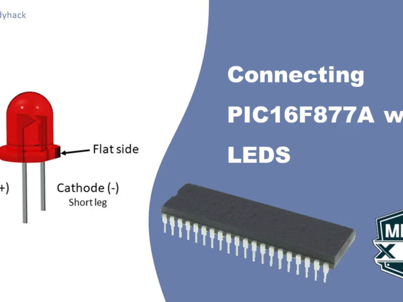
In this tutorial we will explore the concept of connecting your microcontroller with LEDs. This exercise is ideal for beginners who want to gain insight into the practical application of a microcontroller. Throughout the tutorial, you will learn fundamental skills such as configuring GPIO and programming the MCU to blink the LED(s). Follow the simple yet comprehensive steps outlined in this tutorial, and you will be able to harness the power of microcontrollers in no time.
Interfacing a LED with the PIC16F877A
Connecting an LED to one of the pins of a microcontroller sounds easy, especially with a breadboard and some wires. However, before we continue with connecting the LEDs with the microcontroller, we need to know what LEDs exactly are, so that we can put them correctly in our circuit.
Light Emitting Diode (LED)
LEDs are one of the most common electrical components, and we see them in almost all our appliances. They emit light in different colors, including special RGB, and infrared LEDs. These components are mostly used to show an indication of an action, such as the “Power On” light on your PC.
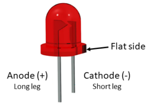
LEDs are two-terminal components with an Anode (+) and a Cathode (-), as depicted in the images above. It is crucial to connect the Anode with the positive terminal, which normally is the power supply. The Cathode, on the other hand, should be connected to the negative terminal. This proper connection ensures optimal LED functionality and safety during operation.
The Cathode and Anode can be visually seen on your LED by the short leg and long leg respectively. Furthermore, there is a flat side on the Cathode to make it more obvious.
Voltage and current requirements
It is important to put a resistor between the anode of the LED and the microcontroller (or between cathode of the LED and ground) to regulate the current flowing through it. LEDs have a few characteristics that can determine the resistance.
The forward voltage of an LED (Light Emitting Diode) is the voltage drop that occurs across the LED when it is conducting current and emitting light. It is the voltage required to turn the LED on and allow current to flow through it, resulting in light emission. The forward voltage is determined by its semiconductor materials and construction, and is typically in the range of 2V for red lights, 2V – 3.5V for green lights and 2.5V – 3.5V for blue and white lights.
It’s important to note that the forward voltage of an LED is not the same as the supply voltage required to power it. To ensure proper operation and prevent excessive current flow, a current-limiting resistor is often used in series with the LED. The resistor helps to drop the excess voltage and regulate the current through the LED, ensuring it operates within its specified range. When designing a circuit with LEDs, it’s crucial to consider the forward voltage along with the desired current (~10mA) and the supply voltage (~5V) to calculate the appropriate current-limiting resistor value.
The resistance can be calculated by the following formula:
\[\frac{V_{supply}-V_{forward}}{I} = R\]
\[\frac{5-2}{0.01} = 300 \Omega\]
The nearest higher standard resistor value is 330 Ω (or any close value that is available).
Connecting 1 LED
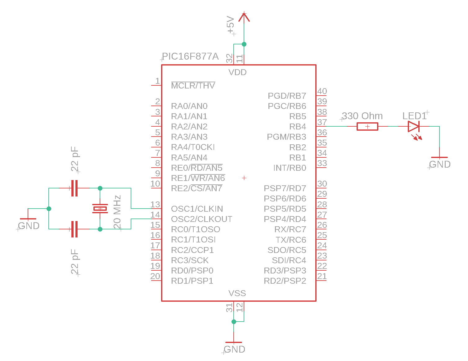
The circuit in the figure below shows the connections that have to be made to set up the microcontroller correctly and have it interfaced with the LED.
To make it function correctly, add the following to your circuit:
- Oscillating crystal of 20 MHz.
- 2 load capacitors that help stabilize the frequency and dampen any higher harmonics. Their values are normally in the range of 10 pF – 33 pF.
- Vdd which is +5V.
- GND, which is connected to the ground of your power supply.
- Resistor, with typical value of 330 Ohm.
- Red LED.
In the code below, we set the pin as an output and create an infinite loop that turns it on and off with half a second delay.
					#define _XTAL_FREQ 20000000 // Define crystal frequency to 20 MHz
#include <xc.h>

// Configuration bits settings
#pragma config FOSC = HS        // External Oscillator, larger than 4 MHz (HS)
#pragma config WDTE = OFF       // Watchdog Timer Disabled
#pragma config PWRTE = ON       // Power-Up Timer Enabled
#pragma config BOREN = OFF      // Brown-out Reset Disabled
#pragma config LVP = OFF        // Low-Voltage Programming Disabled

void main(void) {
    TRISB4 = 0; // Set RB4 as output
    RB4 = 0; // Initialize RB4 low

    while (1) {
        __delay_ms(500); // Delay for half a second (500 milliseconds)
        RB4 = 1; // Turn on RB4 (LED)
        __delay_ms(500); // Delay for half a second (500 milliseconds)
        RB4 = 0; // Turn off RB4 (LED)
    }
}
Connecting 8 LEDs
Creating the circuit for 8 LEDs, shouldn’t be that much different than connecting a single LED, as shown in the figure below. However, we do have to worry about the maximum power the microcontroller can dissipate. Its total power dissipation is 1.0 W; and with 5V powersupply, that leaves a maximum of 200 mA of output current (the maximum input current is also 200 mA, if you’d like to use the microcontroller as a current sink).
Each pin has a maximum output current of 25 mA, which you should avoid as it might damage the circuit. As mentioned before, we’d like to try to keep the current flowing through the LED at around 10 mA. In our circuit we have 8 LEDs and resistors that have a combined maximum output current of 80 mA, which is well below what it can handle.

Analogous to the 1 LED example, here we set the whole PORTB as output with the TRISB register. In the infinite while loop, we start setting pins on and off one by one with a 250 ms delay.
					#define _XTAL_FREQ 20000000 // Define crystal frequency to 20 MHz
#include <xc.h>

// Configuration bits settings
#pragma config FOSC = HS        // External Oscillator (HS)
#pragma config WDTE = OFF       // Watchdog Timer Disabled
#pragma config PWRTE = ON       // Power-Up Timer Enabled
#pragma config BOREN = OFF      // Brown-out Reset Disabled
#pragma config LVP = OFF        // Low-Voltage Programming Disabled

void main(void) {
    TRISB = 0x00; // Set PORTB as output; 0b00000000

    while (1) {
        PORTB = 0x01; // Turn on RB0 LED; 0b00000001
        __delay_ms(250); // Delay
        PORTB = 0x02; // Turn on RB1 LED; 0b00000010
        __delay_ms(250); // Delay
        PORTB = 0x04; // Turn on RB2 LED; 0b00000100
        __delay_ms(250); // Delay
        PORTB = 0x08; // Turn on RB3 LED; 0b00001000
        __delay_ms(250); // Delay
        PORTB = 0x10; // Turn on RB4 LED; 0b00010000
        __delay_ms(250); // Delay
        PORTB = 0x20; // Turn on RB5 LED; 0b00100000
        __delay_ms(250); // Delay
        PORTB = 0x40; // Turn on RB6 LED; 0b01000000
        __delay_ms(250); // Delay
        PORTB = 0x80; // Turn on RB7 LED; 0b10000000
        __delay_ms(250); // Delay
    }
}
Instead of writing such long code, it can be written shorter with a ‘for’ loop. This ‘for’ loop accomplishes the same LED blinking pattern as the previous example but in a more compact and efficient way.
					    while (1) {
        for (unsigned char led = 1; led <= 0x80; led <<= 1) {
            PORTB = led; // Turn on current LED
            __delay_ms(250); // Delay
        }
    }
Let’s break down how the loop works step by step:
- Initialization: The loop starts by initializing a variable
ledof typeunsigned charto a value of1. This value represents the binary pattern to turn on the first LED (RB0). - Condition: The loop continues as long as the value of
ledis less than or equal to0x80.0x80is the hexadecimal representation of10000000in binary, which corresponds to turning on the last LED (RB7). - Iteration: In each iteration of the loop, the value of
ledis left-shifted by one position using the<<=operator. This shifts the bit to the left, effectively turning on the next LED in the sequence. - Body: Inside the loop, the
PORTBregister is set to the current value ofled. This turns on the LED corresponding to the binary pattern represented byled. - Delay: After turning on the LED, there’s a delay of 250 milliseconds using the
__delay_ms()function. This delay controls the duration of time the LED remains on.
The loop continues to iterate through these steps until the condition (led <= 0x80) is no longer met, at which point the sequence starts over from the beginning, creating a repeating pattern of LED blinking. The understanding of this shifting will come at handy in the next tutorial with the 74HC595 shift register, which allows you to control a plural of LEDs with only 3 pins.
Summary
In summary, we learned that a Light Emitting Diode (LED) consists of a cathode and anode, and requires a resistor to regulate current flow and safeguard electronic components. Furthermore, we have examined the setup process of a PIC16F877A microcontroller in connection with LEDs, varying from 1 to 8. Lastly, we have seen a sample program that can program the LED(s) to produce a blinking effect.
In the next tutorial we will explain how to use shift registers as an intermediate element to control a plural of LEDs with a minimum amount of pins, and how to correctly interface with them.
Florius
Hi, welcome to my website. I am writing about my previous studies, work & research related topics and other interests. I hope you enjoy reading it and that you learned something new.
More Posts